Mounting structure for decorative cover of range hood

A technology for installation structure and range hood, applied in the direction of oil fume removal, household stove/stove, heating method, etc., it can solve the problems of fan vibration, variable deformation, affecting product appearance, etc., and achieves the effect of convenient installation

Active Publication Date: 2021-04-16
NINGBO FOTILE KITCHEN WARE CO LTD
View PDF12 Cites 1 Cited by
  • Summary
  • Abstract
  • Description
  • Claims
  • Application Information

AI Technical Summary

Problems solved by technology

However, the method of hanging the decorative cover through the decorative cover hook only provides a supporting force for the decorative cover, because the decorative cover is heavy, and the decorative cover hook itself is longer, which is a cantilever beam, which bears the gravity of the decorative cover. Afterwards, it is easy to degenerate and deform, resulting in a certain gap between the decorative cover and the ceiling, which affects the appearance of the product
Another example is the patent No. 201720314286.X (the authorized announcement number is CN206846830U) disclosed in the Chinese Utility Model Patent "Fixing Structure of Range Hood Decorative Cover", which connects the decorative cover to the fan cover through the elastic extrusion part of the elastic clip. , relying on the friction between the fan cover and the decorative cover to achieve the fixing of the decorative cover, however, during the operation of the range hood, the rotation of the fan produces a large vibration, which will cause a gap between the decorative cover and the fan cover after long-term operation. small relative displacement

Method used


Image

  • Mounting structure for decorative cover of range hood
  • Mounting structure for decorative cover of range hood
  • Mounting structure for decorative cover of range hood

Examples


Embodiment Construction

[0020] The present invention will be further described in detail below in conjunction with the accompanying drawings and embodiments.

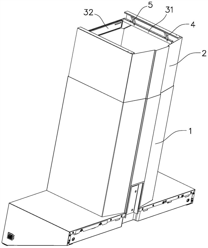
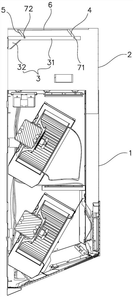
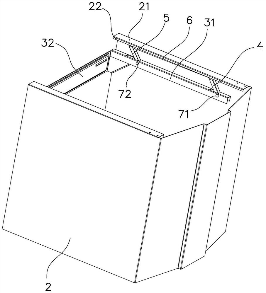
[0021] Such as Figure 1 to Figure 6 As shown, the decorative cover installation structure of the range hood in this embodiment includes a decorative cover 2 , a fixed hanger 3 , a first connecting rod 4 , a second connecting rod 5 and a horizontal support rod 6 .

[0022] The decorative cover 2 is installed on the top of the fan cover 1. The lower part of the decorative cover 2 is set on the inner side of the fan cover 1 and can be pulled up and down relative to the fan cover 1. The decorative cover 2 is used to cover the air outlet cover and the air duct on the top of the range hood (not shown in the figure). The fixed hanger 3 is used to be fixed on the body of wall (not shown in the figure). In the present embodiment, the fixed hanger 3 includes a mounting base 32 and a horizontal hanging arm 31 extending forward from the left and right e...


PUM


Abstract

A decorative cover installation structure for range hoods, including a decorative cover arranged on the top of the fan cover and a fixed hanger for fixing on the wall, the left and right sides of the fixed hanger are respectively provided with horizontal hanging arms extending forward, The horizontal hanging arms are arranged on the left and right sides of the interior of the decorative cover. The first connecting rod, the second connecting rod, the horizontal support rod and the horizontal hanging arm constitute a four-bar linkage mechanism. The left and right sides of the decorative cover are respectively hung on the corresponding horizontal support On the rod, an elastic member that can keep the first connecting rod to rotate upwards and drive the horizontal support rod upwards against the decorative cover is installed between the horizontal hanging arm and the first connecting rod. The advantage of the present invention is that: the hook of the decorative cover is composed of a four-bar linkage mechanism, and the elastic force provided by the elastic member can drive the horizontal support bar to withstand the decorative cover upwards, thereby ensuring the stability of the installation position of the decorative cover and having no gap with the kitchen ceiling. In addition, the installation structure does not need other auxiliary fixing structures, and the installation process does not need to dismantle other components, so the installation is very convenient.

Description

technical field [0001] The invention relates to a range hood, in particular to a mounting structure for a decorative cover of the range hood. Background technique [0002] The decorative cover of the range hood is used to cover the air outlet cover and air duct on the top of the range hood, which plays a role of beauty and decoration. The decorative cover can usually be pulled out from the top of the range hood, and can be adjusted according to the height of the user's house. height adjustment. Various installation structures of decorative covers are disclosed in the prior art, such as "A Installation Structure for Range Hood Decorative Covers" disclosed in the Chinese invention patent application with application number 201610444600.6 (application publication number is CN 106091052 A). The installation structure of the decorative cover of the hood is equipped with a lock on the decorative cover. When installing the decorative cover, there is no need to remove the range hoo...

Claims


Application Information

Patent Timeline
Patent Type & Authority Patents(China)
IPC IPC(8): F24C15/20
CPCF24C15/2071
Inventor 胡涛贺峰李斌
Owner NINGBO FOTILE KITCHEN WARE CO LTD
Why Eureka
Try Eureka