Motor vehicle air filter device and filter element for motor vehicle air filter device
What is Al technical title?
Al technical title is built by PatSnap Al team. It summarizes the technical point description of the patent document.
An air filter device and filter element technology, which is applied in the direction of combustion air/combustion-air treatment, machine/engine, membrane filter, etc., can solve problems such as difficult identification, unwanted air filter devices, and unobtrusive attention, and achieve The effect of convenient and reliable installation
Active Publication Date: 2022-05-17
梅赛德斯-奔驰集团股份公司
View PDF8 Cites 0 Cited by
Summary
Abstract
Description
Claims
Application Information
AI Technical Summary
This helps you quickly interpret patents by identifying the three key elements:
Problems solved by technology
Method used
Benefits of technology
Problems solved by technology
What can happen at this point is that the walls of the filter frame are not resting correctly against the carrying bosses, but are simply pressed against the bosses
This may not be noticeable especially in the housing area of the air filter unit where the protrusions are not clearly visible
In this way, undesired and also poorly recognizable leaks of the air filter can occur
Method used
Image
Click on the blue label to locate the original text in one second.
Reading with bidirectional positioning of images and text.
Examples
Embodiment Construction
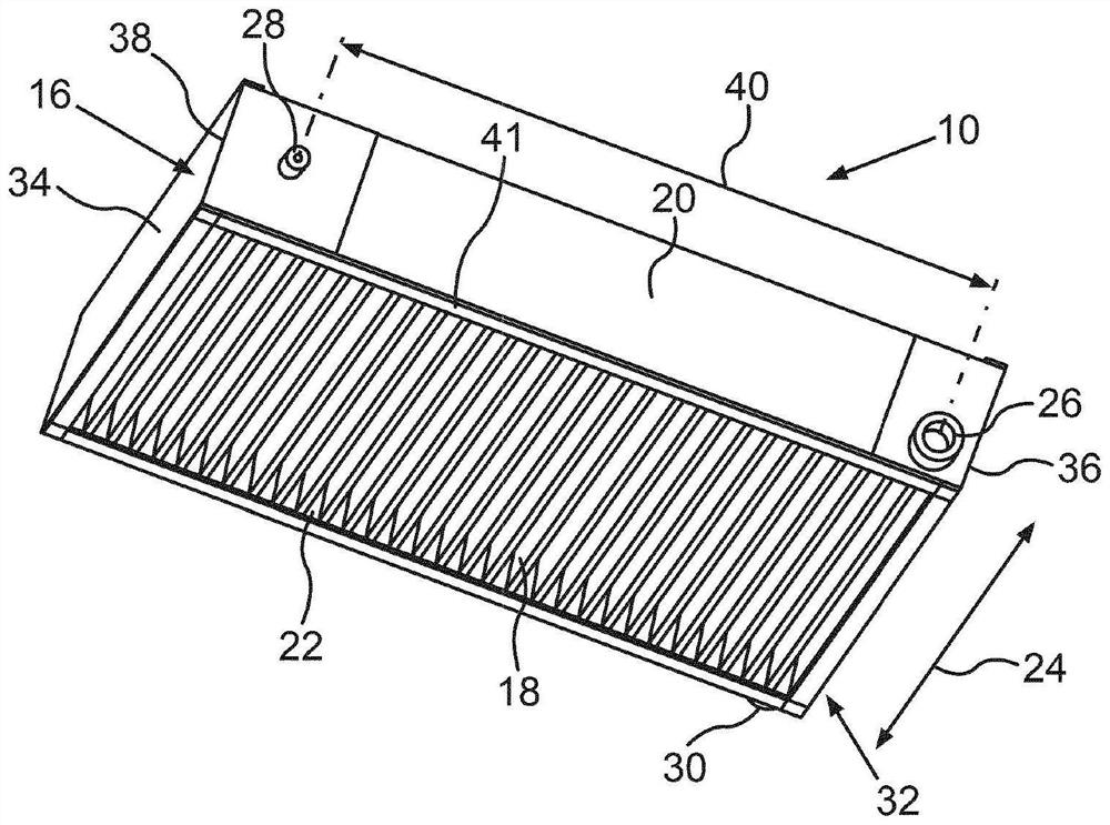
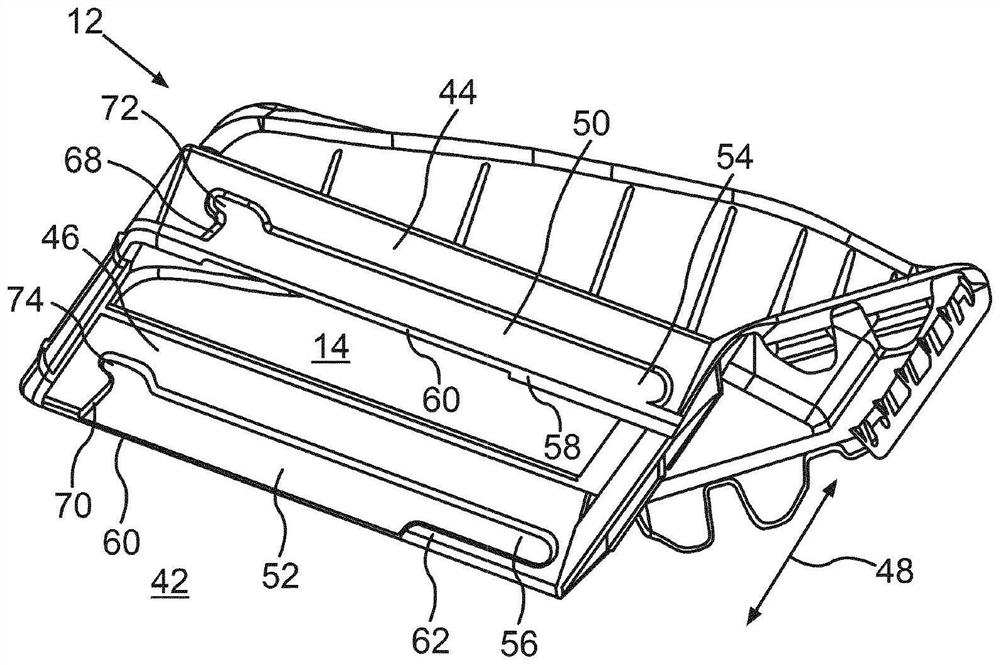
[0048] figure 1 A filter element 10 for a motor vehicle air filter is shown schematically in perspective. The air filtering device comprises a housing 12, the housing is figure 2 is schematically shown in a perspective view. Correspondingly, the housing 12 has a receiving space 14 into which the filter element 10 can be inserted.
[0049] exist figure 1 In the illustrated variant of the filter element 10 , the filter element 10 has a frame 16 which completely surrounds or frames a filter material 18 . In other words, the filter material 18 , in particular designed as a filter cloth, is held within the frame 16 , and the air to be filtered flows through the filter cloth during operation of the air filter device. If the filter element 10 is designed as a pleated filter, as shown here by way of example, the filter material 18 can have a corresponding pleated structure with a large number of folds.
[0050] In the present case, the frame 16 comprises a first side wall 20 and...
PUM
Abstract
The invention relates to an air filter device for a motor vehicle, comprising a housing (12) with a receiving space (14) for a filter element (10). The filter element (10) has a frame (16) which at least partially surrounds a filter material (18) of the filter element (10). The frame (16) comprises a first side wall (20) and a second side wall (22) opposite the first side wall, and a first transverse wall and an opposite second transverse wall (32, 34) connecting the side walls. A first projection (26, 30, 76, 78) projects from the respective side wall (20, 22) near one of the two transverse walls (32, 34). The housing (12) comprises two opposite housing side walls (44, 46), each of which has at least one chute (50, 52, 80, 82, 84, 86), in which a first projection (26, 30, 76, 78) of each side wall (20, 22) of the filter element (10) can be inserted into a chute end region (54, 56, 72, 74, 98, 100, 106, 108) directed in a first direction (64, 102, 104). A second projection (28, 76, 78) protrudes from the side wall (20, 22) in the vicinity of the other of the two transverse walls (32, 34), and wherein the housing side walls (44, 46) each have a second slotted end region (72, 74, 98, 100, 106, 108) which is directed in the opposite direction to the first direction (64, 102, 104) and into which the second projection (28, 76, 78) can be inserted, such that the filter element (10) is located in the receiving space (14) of the housing (12) in the operating position thereof. The side walls (20, 22) can be elastically deformed in such a way that the mutual distance (40) between two projections (26, 28, 30, 76, 78) arranged on the same side wall (20, 22) can be reduced in order to insert the respective second projection (28, 76, 78) into the associated second chute end region (72, 74, 98, 100, 106, 108) along the inwardly directed chute guide side (68, 70, 92, 96, 90, 94) during installation. The invention also relates to a filter element (10) for such an air filter device.
Description
technical field [0001] The invention relates to an air filter device with a filter housing for accommodating a replaceable filter element of a motor vehicle air filter device, wherein the filter housing has two pairs for guiding and supporting the flat filter element The raised chute (Kulisse) on the placed side wall, the filter element consists of a filter web (Filtervlies) held in a frame formed with the side wall. The invention also relates to a filter element for a motor vehicle air filter, which has projections on the side walls. Background technique [0002] In order for the filter element in the housing of the air filter device for a motor vehicle to be able to perform its function reliably, it must be ensured that the filter element is secured tightly and in a positionally stable manner in the housing. [0003] DE 10 2014 004 738 A1 describes a filter element with a box-shaped main body, wherein in the frame wall of the main body made of flexible material there are ...
Claims
Application Information
Patent Timeline
Application Date:The date an application was filed.
Publication Date:The date a patent or application was officially published.
First Publication Date:The earliest publication date of a patent with the same application number.
Issue Date:Publication date of the patent grant document.
PCT Entry Date:The Entry date of PCT National Phase.
Estimated Expiry Date:The statutory expiry date of a patent right according to the Patent Law, and it is the longest term of protection that the patent right can achieve without the termination of the patent right due to other reasons(Term extension factor has been taken into account ).
Invalid Date:Actual expiry date is based on effective date or publication date of legal transaction data of invalid patent.