Display panel and electronic equipment

A display panel and light-emitting display technology, which is applied in the direction of circuits, electrical components, electric solid devices, etc., can solve the problem of reducing the screen ratio of the display screen, so as to enhance the signal passing ability, reduce the degree of interference, and increase the screen ratio. Effect

Active Publication Date: 2020-08-28
MEGVII BEIJINGTECH CO LTD
View PDF5 Cites 3 Cited by
  • Summary
  • Abstract
  • Description
  • Claims
  • Application Information

AI Technical Summary

Problems solved by technology

However, the groove or hole formed on the display screen of the electronic device reduces the screen-to-body ratio of the display screen.

Method used


Image

  • Display panel and electronic equipment
  • Display panel and electronic equipment
  • Display panel and electronic equipment

Examples


Embodiment Construction

[0047] The technical solutions of the present application will be clearly and completely described below in conjunction with the embodiments. Apparently, the described embodiments are part of the embodiments of the present application, not all of them. Based on the embodiments in this application, all other embodiments obtained by persons of ordinary skill in the art without making creative efforts belong to the scope of protection of this application.

[0048]In describing the present invention, it should be understood that the terms "center", "longitudinal", "transverse", "length", "width", "thickness", "upper", "lower", "front", " Orientation indicated by rear, left, right, vertical, horizontal, top, bottom, inside, outside, clockwise, counterclockwise, etc. The positional relationship is based on the orientation or positional relationship shown in the drawings, which is only for the convenience of describing the present invention and simplifying the description, rather tha...


PUM


Abstract

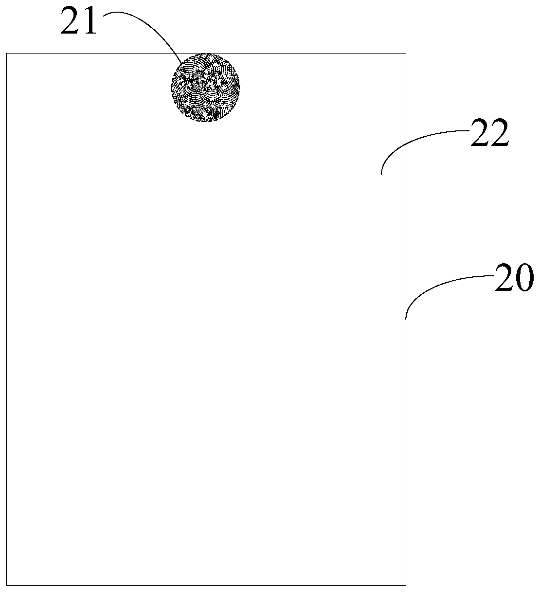
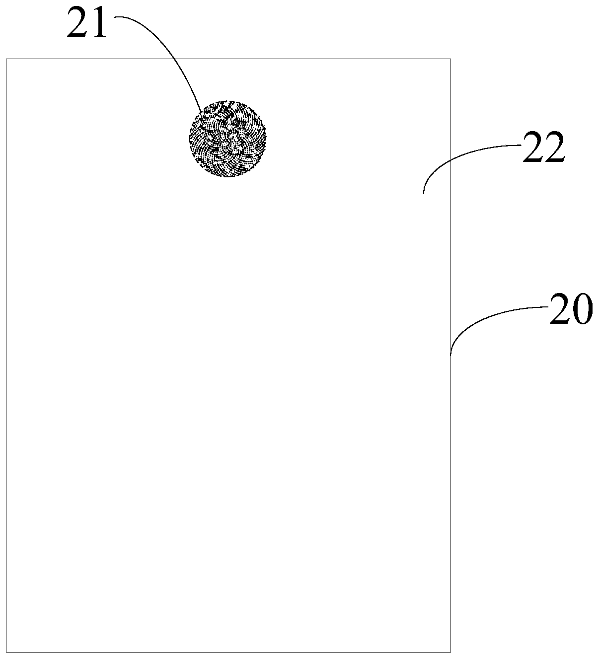
The invention provides a display panel and electronic equipment. The display panel comprises: a substrate; a light-emitting function layer arranged on the substrate, wherein the light-emitting function layer comprises a multiplexing function area, the multiplexing function area comprises at least one multiplexing function sub-area, the multiplexing function sub-area is provided with a plurality offirst light-emitting sub-pixels, and part or all of the plurality of first light-emitting sub-pixels are arranged along a plurality of spiral curves and are arranged in a grid shape. According to thedisplay panel provided by the embodiment of the invention, a plurality of first light-emitting sub-pixels of a multiplexing function sub-region are arranged along a plurality of spiral curves and arearranged in a grid shape, so that the number of diffraction fringe rings formed after a point light source penetrates through a screen can be reduced, the signal passing capacity of the multiplexingfunction area can be enhanced, and the interference degree of signals received or sent by the optical device can be reduced.

Description

technical field [0001] The present application relates to the field of image acquisition technology, in particular to a display panel and electronic equipment. Background technique [0002] With the development of mobile terminal technology and the needs of users, full-screen terminals have become an important development trend. In related technologies, electronic equipment is provided with a front camera, and a slot or hole is generally provided on a display screen of the electronic equipment where the front camera is installed, so that the front camera can collect external images. However, the slots or holes formed on the display screen of the electronic device reduce the screen-to-body ratio of the display screen. Contents of the invention [0003] The purpose of this application is to provide a display panel, electronic equipment and a method for determining the layout of the display panel, which can enhance the signal passing capability of the multiplexing functional...

Claims


Application Information

Patent Timeline
Patent Type & Authority Applications(China)
IPC IPC(8): H01L27/32
CPCH10K59/353H10K59/65
Inventor 徐鲁辉范浩强李帅
Owner MEGVII BEIJINGTECH CO LTD
Why Eureka
Try Eureka