Conveyer and automatic marking press

A transmission device and creasing machine technology, applied in the direction of sending objects, transportation and packaging, thin material processing, etc., can solve the problems of belt deviation, affecting the transmission of paper by the transmission device, shaft and wheel misalignment, etc., to achieve good transmission effect Effect

Pending Publication Date: 2020-09-01
宁波盛世阳光自动化科技有限公司
View PDF0 Cites 0 Cited by
  • Summary
  • Abstract
  • Description
  • Claims
  • Application Information

AI Technical Summary

Problems solved by technology

The transmission device of this kind of prior art has the following defects: if the matching precision between the driving wheel and the driving shaft or between the driven wheel and the driven shaft is not up to the standard, the phenomenon of non-concentricity is prone to occur between the shaft and the wheel, and the belt There will still be a phenomenon of deviation, which will affect the conveying device to convey the paper, thus affecting the normal use of the automatic creasing machine

Method used


Image

  • Conveyer and automatic marking press
  • Conveyer and automatic marking press
  • Conveyer and automatic marking press

Examples


Embodiment 1

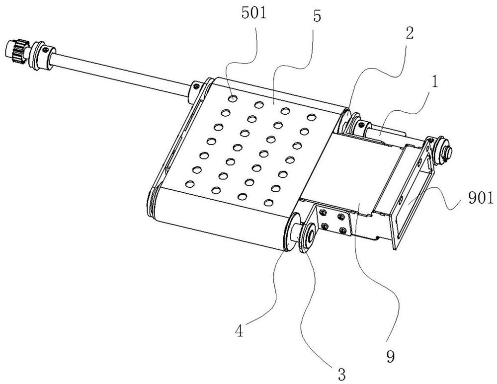
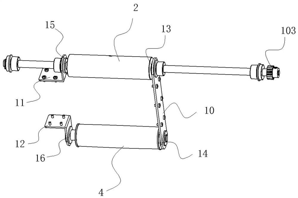
[0031] The invention discloses a conveying device comprising a driving shaft 1, a driving wheel 2, a driven shaft 3, a driven wheel 4 and a conveyor belt 5.

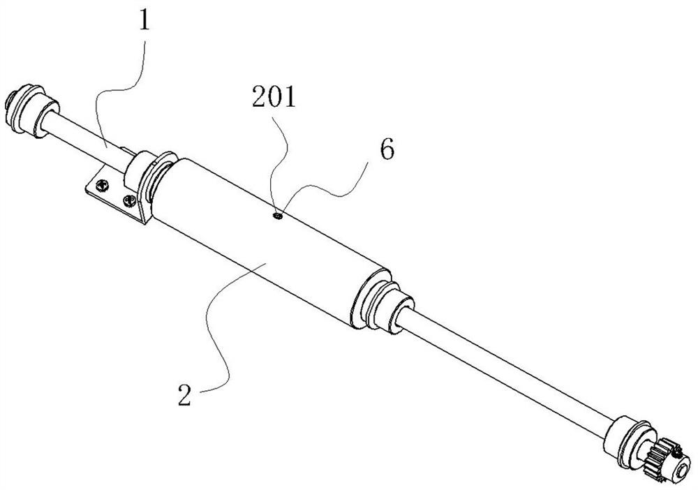
[0032] The driving shaft 1 is provided with a positioning hole 101 or a positioning groove. In this specific embodiment, the driving shaft 1 is provided with a positioning hole 101, and the positioning hole 101 is radially arranged. The driving wheel 2 is a hollow cylindrical structure. The driving wheel 2 is provided with a mounting hole 201 at a position corresponding to the positioning hole 101. The inner wall of the mounting hole 201 is provided with an inner wall. Thread. The driving wheel 2 is sleeved outside the driving shaft 1, and a gap is left between the driving wheel 2 and the driving shaft 1. The driving wheel 2 and the driving shaft 1 are connected by a connecting component, and the connecting component includes a connecting piece 6. The connecting member 6 has a cylindrical structure, one end of the connect...

Embodiment 2

[0036] Compared with the transmission device of the first embodiment, the transmission device disclosed in this embodiment has the following differences: the structure of the driving shaft and the driving wheel of the transmission device of this embodiment is different from that of the driven shaft and the driven wheel of the transmission device of the first embodiment. The structure is the same; the structure of the driven shaft and the driven wheel of the transmission device of this embodiment is the same as the structure of the driving shaft and the driving wheel of the transmission device of the first embodiment.

[0037] The conveyor belt is connected between the driving wheel and the driven wheel. The rotation of the driving shaft will drive the driving wheel to rotate. The driven shaft and the driven wheel are driven by the driving wheel and the conveyor belt to rotate. The driving wheel will float a little at the beginning under the action of centrifugal force, and it will...

Embodiment 3

[0039] Compared with the transmission device of the first embodiment, the transmission device disclosed in this embodiment has the following differences: the structure of the driven shaft and the driven wheel of the transmission device of this embodiment is different from that of the driving shaft and driving wheel of the transmission device of the first embodiment. The structure is the same. That is, the structure of the driving wheel and the driving shaft and the structure of the driven wheel and the driven shaft of the transmission device of this embodiment are all movably connected.

[0040] The conveyor belt is connected between the driving wheel and the driven wheel. The rotation of the driving shaft will drive the driving wheel to rotate. The driven shaft and the driven wheel are driven by the driving wheel and the conveyor belt to rotate. The driving wheel and the driven wheel will fluctuate a little at the beginning due to the centrifugal force. The shaft keeps coaxial ...


PUM


Abstract

The invention discloses a conveyer and an automatic marking press. The conveyer comprises a driving shaft, a driven shaft and a conveying belt; the driving shaft is driven by a driving device to rotate; and the conveying belt is connected between the driving shaft and the driven shaft. The conveyer is characterized in that a driving wheel is arranged outside the driving shaft in a sleeving mode, agap is reserved between the driving wheel and the driving shaft, a connecting assembly is disposed between the driving wheel and the driving shaft, and the movable gap is reserved between the drivingwheel and the driving shaft through the connecting assembly so that the coaxiality between the driving wheel and the driving shaft can be automatically adjusted during rotation of the driving wheel and the driving shaft; and / or a driven wheel is arranged outside the driven shaft in a sleeving mode, a gap is reserved between the driven wheel and the driven shaft, a connecting assembly is disposedbetween the driven wheel and the driven shaft, and the movable gap is reserved between the driven wheel and the driven shaft through the connecting assembly so that the coaxiality between the driven wheel and the driven shaft can be automatically adjusted during rotation of the driven wheel and the driven shaft. By means of the conveyer and the automatic marking press, the effect that the conveying belt is kept in the middle position and does not deviate all the time can be guaranteed, and the conveying effect is good.

Description

Technical field [0001] The invention relates to paper processing equipment, and more specifically to a conveying device and an automatic creasing machine. Background technique [0002] Automatic creasing machines are frequently used in cardboard processing, which can complete one or more creasing for business cards, photos, greeting cards, color pages and covers at a time. The automatic creasing machine has the advantages of full creases without breaking; the creasing saves time and effort, is convenient and fast, etc. It is a graphic production center, library, small and medium printing enterprise, design institute, graphic shop, publishing center, government Indispensable equipment for agencies, large enterprises and other institutions. [0003] The automatic creasing machine includes a body, and a paper conveying device is arranged on the body. The paper conveying device includes a paper conveying table, a conveying device and an air suction device. The conveying device and t...

Claims


Application Information

Patent Timeline
Patent Type & Authority Applications(China)
IPC IPC(8): B65H29/16B65H29/24
CPCB65H29/16B65H29/242
Inventor 杨明明
Owner 宁波盛世阳光自动化科技有限公司
Why Eureka
Try Eureka