
Central flue fume exhaust system and real-time automatic control method thereof

A smoke exhaust system and flue technology, applied in the direction of heating, oil fume removal, household heating, etc., can solve the problems of large system resistance, large user flow deviation, difficulty in adapting to various flue environments, etc., to ensure smooth exhaust Effects of smoke and avoidance of cross-odour

Pending Publication Date: 2020-09-01
NINGBO FOTILE KITCHEN WARE CO LTD
View PDF0 Cites 0 Cited by
  • Summary
  • Abstract
  • Description
  • Claims
  • Application Information

AI Technical Summary

Problems solved by technology

[0003] The current method of using a common flue booster fan to exhaust smoke, and adjusting the actual flow rate by adjusting the angle of the valve plate is simply to adjust the flow at a preset fixed angle, which is difficult to adapt to various flue environments, and the angle is adjusted for a specific flue The CFD calculation workload is very large, and it is difficult to customize the installation of each floor in the actual environment, resulting in large deviations in user traffic; in addition, this method is often adjusted based on the lowest floor traffic. If the lowest start-up floor is not the lowest floor , it is easy to cause the system resistance to be too large and affect the energy consumption of the host
In addition, the use of a single public flue to exhaust smoke cannot avoid the occurrence of flue odors

Method used


Image

  • Central flue fume exhaust system and real-time automatic control method thereof
  • Central flue fume exhaust system and real-time automatic control method thereof
  • Central flue fume exhaust system and real-time automatic control method thereof

Examples


Embodiment Construction

[0028] The present invention will be further described in detail below in conjunction with the accompanying drawings and embodiments.

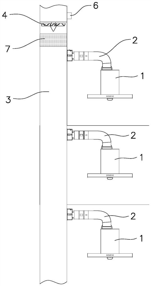
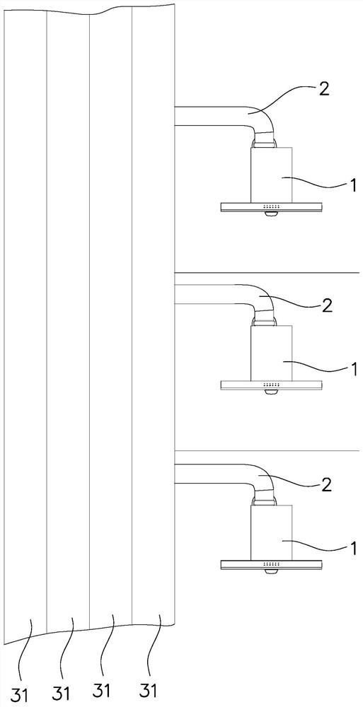
[0029] Such as Figure 1 to Figure 3 As shown, the central flue smoke exhaust system of this embodiment includes range hoods 1 installed on different floors, and the air outlets of each range hood 1 are connected to the common flue 3 through their respective smoke pipes 2, and the common smoke The outlet of Road 3 is equipped with a flue fan 4 . A filtering device 7 is installed in the public flue 3 near the air inlet of the flue fan 4, and the oil fume is purified by the filtering device 7.

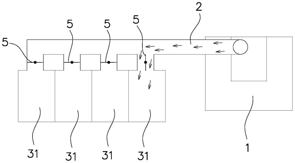
[0030] The public flue 3 is divided into a plurality of independent sub-flues 31, the number of the sub-flues 31 is greater than the number of floors, so that the range hood 1 on each floor can be assigned at least one sub-flue 31, and each sub-flue A valve 5 is installed at the air inlet of the flue 31 . The valve 5 is opened, the air outlet of the r...


PUM


Abstract

The invention provides a central flue fume exhaust system. The central flue fume exhaust system comprises range hoods mounted on different floors. An air outlet of each range hood communicates with acommon flue through a smoke tube. A flue fan is mounted at an outlet of the common flue. The central flue fume exhaust system is characterized in that the common flue is divided into a plurality of independent sub-flues; the number of the sub-flues is greater than that of the floors; at least one sub-flue is allocated to the range hood on each floor; and a valve is mounted at an air inlet of eachsub-flue. The invention further discloses a real-time automatic control method of the central flue fume exhaust system. The central flue fume exhaust system has the advantages that the common flue isdivided into the multiple independent sub-flues, so that each user uses the independent sub-flue, and the situation of smell confusion can be avoided. Moreover, the sub-flues can be opened and closedaccording to resistance of the range hoods on the corresponding floors so as to ensure smooth fume exhausting.

Description

technical field [0001] The invention relates to a central flue system, in particular to a central flue smoke exhaust system and a real-time automatic control method thereof. Background technique [0002] At present, the floors of newly-built buildings in cities are generally higher and higher. Since the outlets of high-rise public flues are generally set on the top of the floors, the switching status of the range hoods of each user's home will affect the resistance of the system outlet, making the smoke exhaust situation of users at the bottom poor. . In recent years, the user-side adjustable angle valve combined with the centralized filtration and discharge of the flue fan at the outlet of the roof flue has begun to be applied in some well-decorated real estate. Flow distribution, to a certain extent, can solve the poor smoke exhaust situation of bottom users, and at the same time effectively control the flow rate and noise of the entire flue system. [0003] The current ...

Claims


Application Information

Patent Timeline
Patent Type & Authority Applications(China)
IPC IPC(8): F24C15/20
CPCF24C15/2021
Inventor 邱骁哲
Owner NINGBO FOTILE KITCHEN WARE CO LTD
Learn More