Fixing structure of gastroscope tube in gastroenterology department
A fixed structure, gastroenterology technology, which is applied in the field of gastroenterology and can solve the problems of inability to fix the gastroscope tube, inability to examine patients, and patient discomfort.
- Summary
- Abstract
- Description
- Claims
- Application Information
AI Technical Summary
Problems solved by technology
Method used
Image
Examples
Embodiment 1
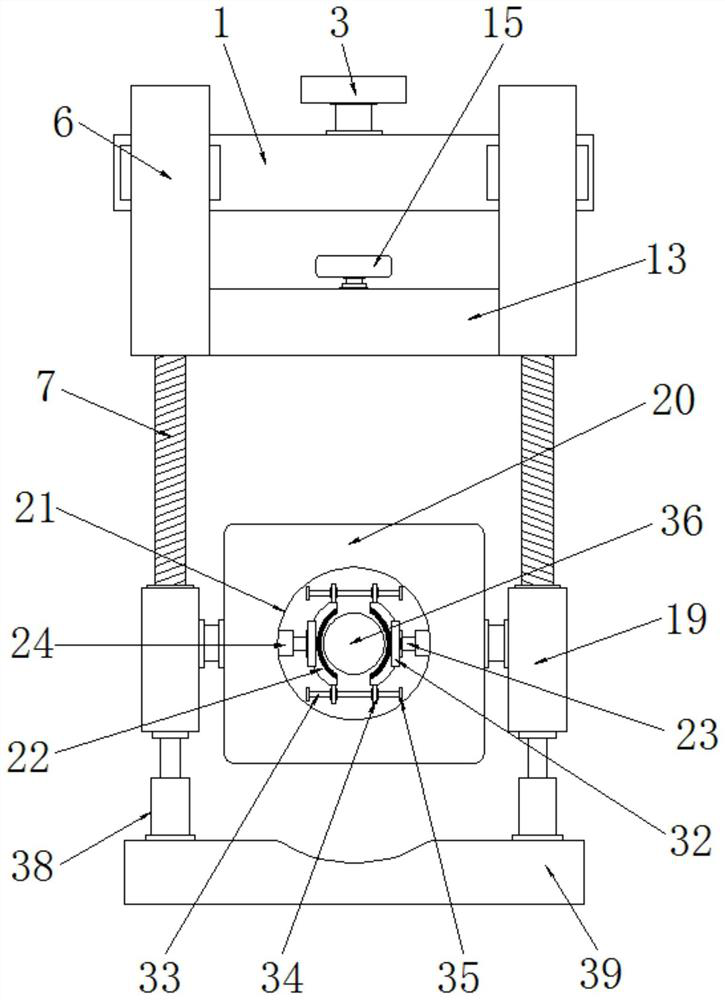
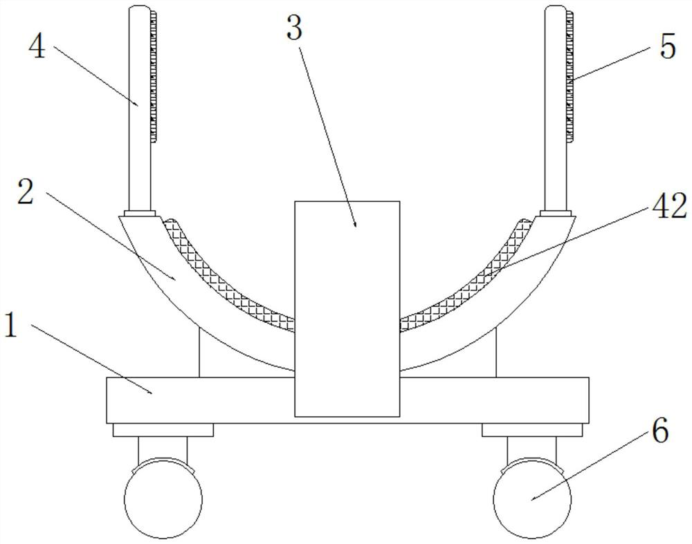
[0030] Embodiment one, such as Figure 1-9As shown, the gastroenterology gastroscope tube fixing structure according to the embodiment of the present invention includes a top plate 1, an arc-shaped plate 2 is installed on one side of the top plate 1, a baffle plate 3 is installed in the middle of the top of the top plate 1, and the One end of the baffle plate 3 extends to the inside of the arc structure of the arc plate 2, and the end of the arc plate 2 away from the top plate 1 is equipped with a fixing bar 4, and one side of the fixing bar 4 All are equipped with Velcro 5, through the interaction between the arc-shaped plate 2 and the baffle plate 3 and the fixing strip 4 and the Velcro 5, people can better interact with the patient's head when using. fixed, so that the gastroscope tube can be better fixed, and then people’s needs can be better met. The side of the top plate 1 away from the arc plate 2 is symmetrically equipped with a sleeve rod-6, so Threaded rods 7 are in...
Embodiment 2
[0031] Embodiment two, such as figure 2 As shown, the side of the arc-shaped plate 2 away from the top plate 1 is equipped with an arc-shaped sponge partition 42; through the arc-shaped sponge partition 42, people can achieve a good sense of comfort when wearing and fixing, thereby It is convenient to better perform the fixing operation of the gastroscope tube, and thus it is convenient to better meet people's use needs.
Embodiment 3
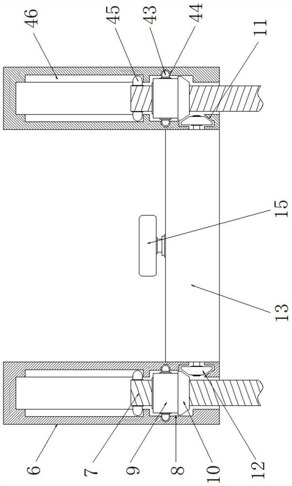
[0032] Embodiment three, such as image 3 As shown, the two sides of the threaded sleeve 9 are equipped with movable clamping blocks three 43, and the inner side of the installation groove 8 is provided with a position corresponding to the movable clamping block three 43 and the movable clamping block three 43. Block three 43 compatible movable card slot three 44; both sides of the top of the threaded rod 7 are equipped with positioning blocks 45, and the inside of the sleeve rod one 6 is located above the installation groove 8 and the The position corresponding to the positioning block 45 is provided with a positioning slot 46 that is compatible with the positioning block 45; through the three movable blocks 43 and the three movable slots 44, the threaded sleeve 9 can be more Rotate stably, and through the interaction between the positioning block 45 and the positioning slot 46, the downward movement distance of the threaded rod 7 can be limited, and the situation of placing ...
PUM
 Abstract
Description
Claims
Application Information
 - R&D
- Intellectual Property
- Life Sciences
- Materials
- Tech Scout
- Unparalleled Data Quality
- Higher Quality Content
- 60% Fewer Hallucinations
Browse by: Latest US Patents, China's latest patents, Technical Efficacy Thesaurus, Application Domain, Technology Topic, Popular Technical Reports.
© 2025 PatSnap. All rights reserved.Legal|Privacy policy|Modern Slavery Act Transparency Statement|Sitemap|About US| Contact US: help@patsnap.com


