
Finger structure and robot

A finger and middle finger technology, applied in the field of finger structure and robotics, can solve the problem that the finger structure is difficult to show, and achieve the effect of overall improvement

Active Publication Date: 2020-09-04
UBTECH ROBOTICS CORP LTD
View PDF8 Cites 2 Cited by
  • Summary
  • Abstract
  • Description
  • Claims
  • Application Information

AI Technical Summary

Problems solved by technology

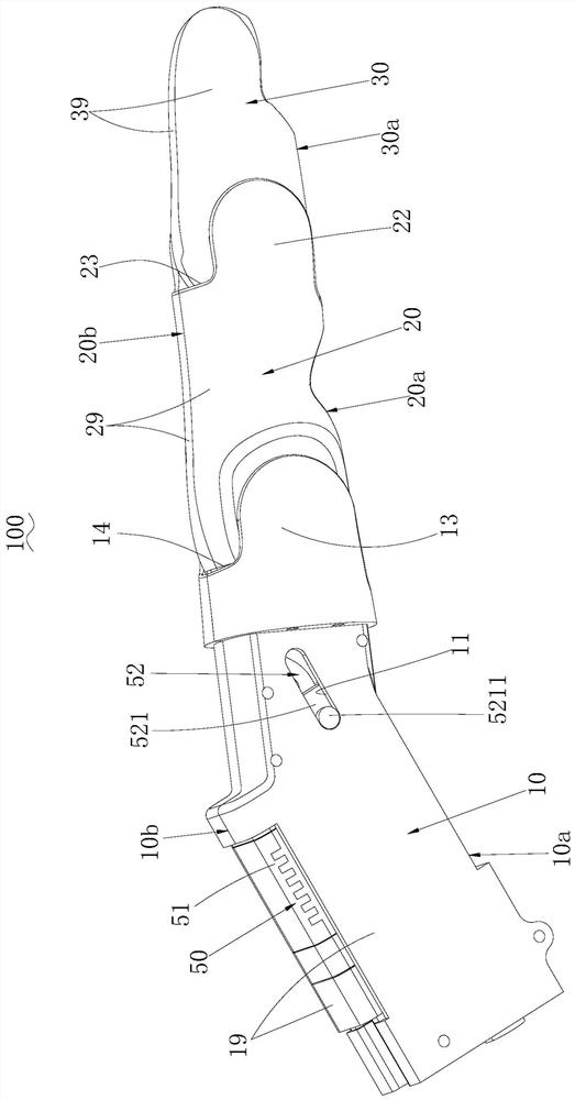
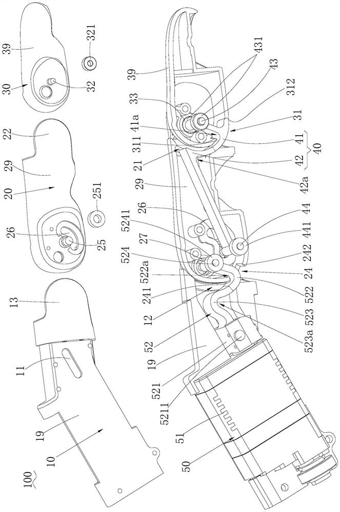
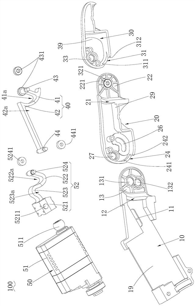
[0003] The purpose of the embodiments of the present application is to provide a finger structure and a robot to solve the technical problems that the existing finger structure needs to be provided with a relatively large opening for the connecting rod to pass through, and the finger structure is difficult to show a certain degree of elasticity to absorb shocks

Method used


Image

  • Finger structure and robot
  • Finger structure and robot
  • Finger structure and robot

Examples


Embodiment Construction

[0038] In order to make the technical problems, technical solutions and beneficial effects to be solved by the present application clearer, the present application will be further described in detail below in conjunction with the accompanying drawings and embodiments. It should be understood that the specific embodiments described here are only used to explain the present application, and are not intended to limit the present application.

[0039] In the description of the embodiments of the present application, it should be understood that the terms "length", "width", "upper", "lower", "front", "rear", "left", "right", "vertical ", "horizontal", "top", "bottom", "inner", "outer" and other indicated orientations or positional relationships are based on the orientations or positional relationships shown in the drawings, and are only for the convenience of describing the embodiments of the present application and simplifying Describes, but does not indicate or imply that the dev...


PUM


Abstract

The invention belongs to the technical field of robot parts, and relates to a finger structure and a robot. In the finger structure, a near knuckle shell, a middle knuckle shell, a far knuckle shell and a connecting rod form a four-bar mechanism, the near knuckle shell is taken as a fixing frame, a driving assembly drives the middle knuckle shell to swing, the far knuckle shell is linked with theconnecting rod, the far knuckle shell swings in the swinging direction of the middle knuckle shell, and whole bending and straightening action of the finger structure is achieved. A transmission rod is provided with a first bending arm, and a notch of the first bending arm faces the back surface of the near knuckle shell. When the finger structure is straightened, in other words, the near knuckleshell is flush with the middle knuckle shell, and the inner wall of the near end of the middle knuckle extends into the bottom of the notch of the first bending arm, so that the inner wall of the nearend of the middle knuckle can be closer to the central position of a near end opening. The near end opening of the finger structure can be made relatively small, so that the integrality of the appearance of the middle finger shell is improved. Due to the fact that the transmission rod is provided with the first bending arm, when the far knuckle shell or the middle knuckle shell is impacted, the transmission rod can exhibit elasticity and absorb impact.

Description

technical field [0001] The application belongs to the technical field of robot components, and in particular relates to a finger structure and a robot. Background technique [0002] At present, the finger structure of the robot is usually provided with a connecting rod between two adjacent knuckle shells, and the two ends of the connecting rod are respectively connected to the two knuckle shells, so as to realize the transmission of the two knuckle shells. Due to the existence of the connecting rod, the knuckle case should be provided with a relatively large opening for the connecting rod to pass through, that is, the knuckle case will be cut a lot, which will make the appearance of the knuckle case less complete. In addition, since the connecting rod belongs to a one-degree-of-freedom system, when the finger structure is impacted, it is difficult for the connecting rod to exhibit certain elasticity to absorb the impact. Contents of the invention [0003] The purpose of t...

Claims


Application Information

Patent Timeline
IPC IPC(8): B25J15/08B25J17/02
CPCB25J15/08B25J17/0258
Inventor 赵坤雷谢铮石炜智陈明华安昭辉熊友军
Owner UBTECH ROBOTICS CORP LTD
Learn More