
Automatic plastic buckle binding equipment

A technology of rubber buttons and equipment, which is applied in the direction of nailing tools, staple nailing tools, manufacturing tools, etc., and can solve the problems of low efficiency and insufficient safety of rubber button nailing operations

Inactive Publication Date: 2020-09-04
惠州中记家具制造有限公司
View PDF5 Cites 2 Cited by
  • Summary
  • Abstract
  • Description
  • Claims
  • Application Information

AI Technical Summary

Problems solved by technology

[0004] Based on this, it is necessary to provide an automatic glue button nailing equipment for the technical problems of low efficiency and insufficient safety of glue button nailing operations

Method used


Image

  • Automatic plastic buckle binding equipment
  • Automatic plastic buckle binding equipment
  • Automatic plastic buckle binding equipment

Examples


Embodiment Construction

[0025] In order to make the above objects, features and advantages of the present invention more comprehensible, specific implementations of the present invention will be described in detail below in conjunction with the accompanying drawings. In the following description, numerous specific details are set forth in order to provide a thorough understanding of the present invention. However, the present invention can be implemented in many other ways different from those described here, and those skilled in the art can make similar improvements without departing from the connotation of the present invention, so the present invention is not limited by the specific embodiments disclosed below.

[0026] In describing the present invention, it should be understood that the terms "center", "longitudinal", "transverse", "length", "width", "thickness", "upper", "lower", "front", " Back", "Left", "Right", "Vertical", "Horizontal", "Top", "Bottom", "Inner", "Outer", "Clockwise", "Counte...


PUM


Abstract

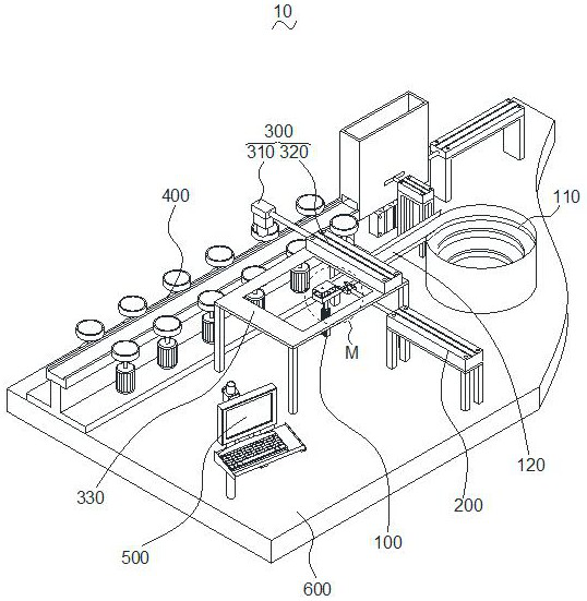
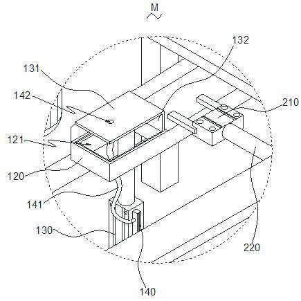
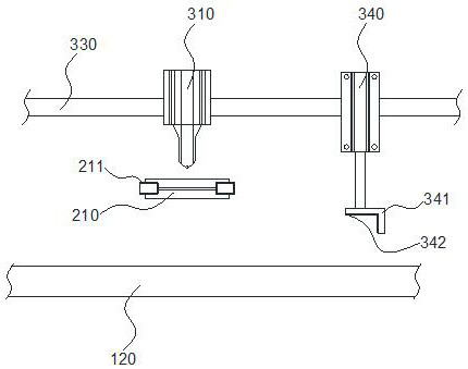
The invention provides automatic plastic buckle binding equipment which comprises a vibration conveying mechanism, a clamping mechanism, a binding mechanism, a conveying mechanism, a control mechanismand a workbench. The vibration conveying mechanism includes a vibrating disk, a conveying track, and a supporting cylinder. The vibrating disk is connected to the conveying track. The conveying trackis provided with a supporting slot, the supporting cylinder is provided with a supporting plate, the supporting plate abuts against the conveying track at the supporting slot, and the supporting cylinder is located vertically below the supporting slot. The clamping mechanism includes a clamping cylinder and an electric push rod. The electric push rod is in drive connection with the clamping cylinder. The binding mechanism comprises a nail spraying gun and a telescopic cylinder. The telescopic cylinder is in drive connection with the nail spraying gun and is connected with the workbench, and the nail spraying gun is located above the conveying mechanism. The control mechanism is electrically connected with the vibrating disk, the supporting cylinder, the electric push rod, the nail spraying gun and the telescopic cylinder. According to the automatic plastic buckle binding equipment, automatic binding operation of plastic buckles and wood boards is achieved, and binding operation efficiency and safety are improved.

Description

technical field [0001] The invention relates to the technical field of rubber button assembly equipment, in particular to an automatic rubber button nailing equipment. Background technique [0002] In the furniture manufacturing industry, especially in the production process of the sofa, many wooden boards and glue buttons are needed. Several wooden boards are used to form the frame of the sofa. It is used to fix the spring inside the sofa. At present, the nailing of wooden boards and rubber buttons is often done manually. The staff uses a nail gun to nail the rubber buttons into the wooden boards, thereby completing the connection and assembly of the wooden boards and the rubber buttons. [0003] However, through manual nailing, the staff fixes the glue button on the wooden board with one hand, and controls the nail spray gun with the other hand, which is very prone to safety accidents. In addition, the efficiency of manual binding operation is low, the labor cost is high...

Claims


Application Information

Patent Timeline
IPC IPC(8): B27F7/02B27F7/05
CPCB27F7/02B27F7/05
Inventor 叶孟霆
Owner 惠州中记家具制造有限公司
Learn More