
Motion connecting structure

A technology of motion connection and connector, which is applied in transportation and packaging, pipes/pipe joints/pipes, measuring instrument components, etc. The effect of improving adaptability

Pending Publication Date: 2020-09-04
中科艾迈克精密机电制造(苏州)有限公司
View PDF0 Cites 0 Cited by
  • Summary
  • Abstract
  • Description
  • Claims
  • Application Information

AI Technical Summary

Problems solved by technology

[0002] At present, the detection devices used on the track and in the pipeline are detection trolleys one by one. When the trolley moves along the track or chute, the rollers on the trolley move in the same plane and conduct in a straight line. If the track deviates, the trolley The front and rear rollers are easy to get stuck in the same plane, that is, the adaptability of the inspection trolley is not strong, which affects the normal operation of the inspection. When the track is inclined or spiral, the detection difficulty increases, and this inspection trolley can no longer Meet the detection conditions

Method used


Image

  • Motion connecting structure
  • Motion connecting structure
  • Motion connecting structure

Examples


Embodiment

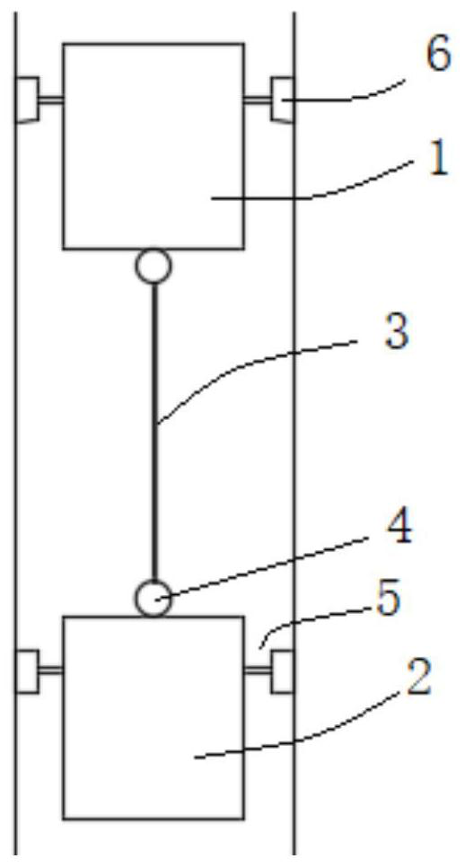
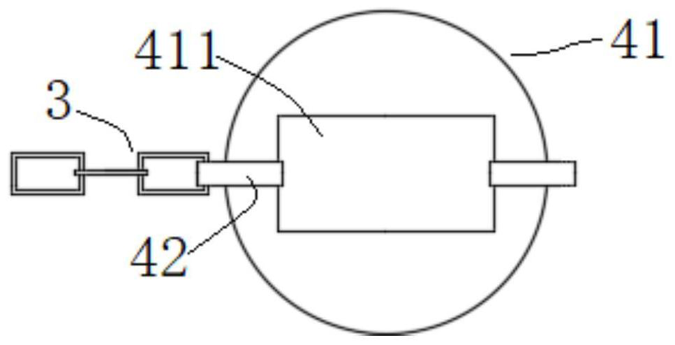
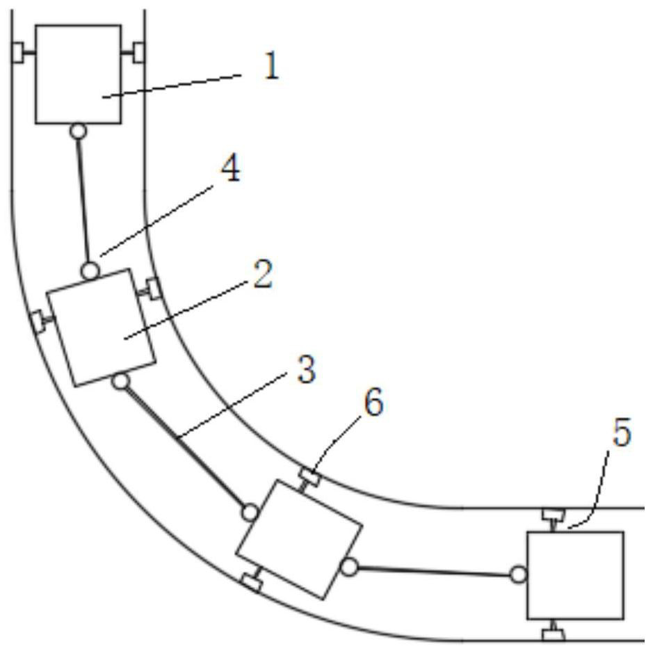
[0036] See Figure 1-3 , The present invention provides a kinematic connection structure, including a number of detection units connected in sequence, the detection unit includes a first detection device 1 and a second detection device 2,

[0037] The first detection device 1 and the second detection device 2 are both equipped with sliding components,

[0038] It also includes a connecting component, which includes a connecting piece 3 and a connecting seat 4 respectively connected to two ends of the connecting piece 3;

[0039] The connecting assembly is connected to the first detection device 1 and the second detection device 2 through the connection base 4 respectively.

[0040] In an embodiment, the sliding component may be a plurality of wheel sets, the wheel set includes a connecting shaft 5, and two rollers 6 connected at both ends of the connecting shaft 5,

[0041] The connecting shaft 5 is installed on the first detecting device 1 and the second detecting device 2, and the ax...


PUM


Abstract

The invention discloses a motion connecting structure, which comprises a plurality of detection units which are connected in sequence. Each detection unit comprises a first detection device and a second detection device, wherein the first detection devices and the second detection devices are provided with sliding assemblies; the motion connecting structure further comprises a connecting assembly,and the connecting assembly comprises a connecting piece and connecting bases connected with the two ends of the connecting piece respectively; and the connecting assembly is connected with the firstdetection device and the second detection device through the connecting bases. According to the motion connecting structure, the adaptability of the detection device can be improved, so that the detection device adapts to a twisted spiral track, the balance of the detection device is kept on the spiral track, and the problem of rollover or roller jamming is avoided.

Description

Technical field [0001] The invention relates to a movement connection structure, in particular to a movement connection structure for a detection device. Background technique [0002] At present, the detection devices used on the track and in the pipeline are the detection trolleys one by one. When the trolley moves along the track or the chute, the rollers on the trolley move in the same plane and conduct linearly. If the track is offset, the trolley The front and rear rollers are easy to jam in the same plane, that is, the adaptability of the detection car is not strong, which affects the normal operation of the detection operation. When the track is inclined or spiral, the detection difficulty increases, and this detection car is no longer possible. Meet the testing conditions. [0003] Therefore, it is urgent to propose a new technical solution to solve the above problems. Summary of the invention [0004] The purpose of the present invention is to solve the problems existing ...

Claims


Application Information

Patent Timeline
Patent Type & Authority Applications(China)
IPC IPC(8): G01D21/02G01D11/00G01B21/02G01B21/14G01B21/00B61K9/02F16L55/28F16L101/30
CPCB61K9/02F16L55/28F16L2101/30G01B21/00G01B21/02G01B21/14G01D11/00G01D21/02
Inventor 李艺袁宇清
Owner 中科艾迈克精密机电制造(苏州)有限公司
Learn More