
Drop test machine

A testing machine and adjustment mechanism technology, applied in impact testing, testing of machine/structural components, measuring devices, etc., can solve problems such as low testing efficiency and inconvenient operation

Pending Publication Date: 2020-09-04
淮安杰鼎唐科技有限公司
View PDF0 Cites 0 Cited by
  • Summary
  • Abstract
  • Description
  • Claims
  • Application Information

AI Technical Summary

Problems solved by technology

[0004] The purpose of the present invention is to provide a drop testing machine to alleviate the problem that in the prior art, when the drop angle is changed to re-perform the drop detection test on the package, the package will roll on the ground after falling, and the package will stop completely. The obvious technical problems of inconvenient operation and low testing efficiency exist in the process of manually picking up the package after rolling

Method used


Image

  • Drop test machine
  • Drop test machine
  • Drop test machine

Examples


Embodiment 1

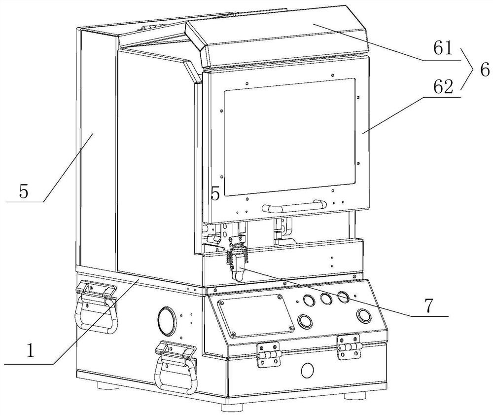
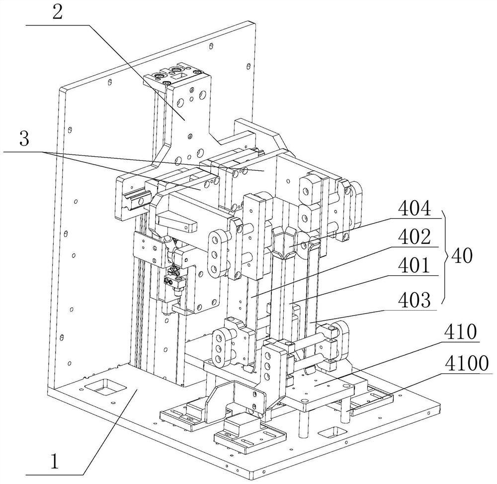
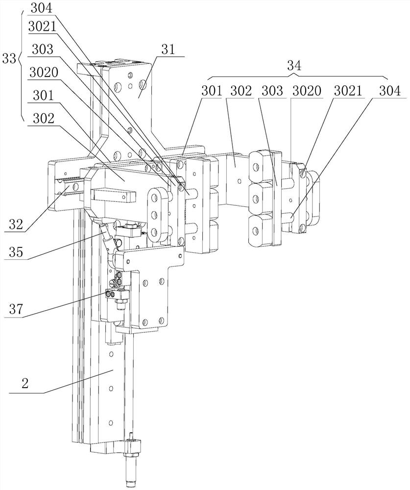
[0051] The present embodiment provides a kind of drop testing machine, refer to Figure 1 to Figure 3 , the drop test machine includes a base 1, a lifting device 2, a clamping device 3 and an enclosure device; the clamping device 3 is installed on the lifting device 2, and is configured to be able to clamp or release the package; the lifting device 2 is installed on the base 1; the enclosure device includes a plurality of longitudinal enclosures connected to the base 1 at the position below the clamping device 3 , and surrounded by a plurality of longitudinal enclosures to form a fence 40 .


PUM


Abstract

The invention provides a drop test machine, which relates to the technical field of product packaging and transportation, and comprises a base, a lifting device, a clamping and placing device and a fence device, wherein the clamping and placing device is mounted on the lifting device and is configured to be capable of clamping or releasing a packaging piece; the lifting device is mounted on the base; the fence device comprises a plurality of longitudinal fences, the longitudinal fences are connected to the portion, located below the clamping and placing device, of the base, and the longitudinal fences form a fence in a surrounding mode. The invention solves the following technical problems: in the prior art, when the throwing-off angle is changed to carry out the drop detection test on thepackaging piece again, the packaging piece rolls on the ground after falling down, and after the packaging piece completely stops rolling, the packaging piece is picked up manually again, so that obvious operation is inconvenient, and the test efficiency is low.

Description

technical field [0001] The invention relates to the technical field of product packaging and transportation, in particular to a drop tester. Background technique [0002] The drop test machine is mainly used to assess the degree of impact of the product package on the actual transportation, loading and unloading process, and to evaluate the impact resistance strength of the package during the handling process and the rationality of the packaging design, which is conducive to the discovery of transportation risks and packaging loopholes; The drop tester currently used usually includes a clamping arm and a lifting mechanism. The clamping arm is installed on the lifting mechanism to clamp the package on the clamping arm. The lifting mechanism raises the clamping arm holding the package to a high place, and then The clamping arm releases the package from a high place to make the package fall freely, and then observe the damage of the package to evaluate the impact resistance of ...

Claims


Application Information

Patent Timeline
Patent Type & Authority Applications(China)
IPC IPC(8): G01M7/08G01N3/303
CPCG01M7/08G01N3/303
Inventor 高征陈龙许兵兵
Owner 淮安杰鼎唐科技有限公司
Learn More