Unlock instant, AI-driven research and patent intelligence for your innovation.

Clamping device for machining reeling device

A technology of clamping device and force coiler, which is applied in the direction of workpiece clamping device and manufacturing tools, can solve the problems of vibration of force coiler, affecting the clamping effect, cleaning of sliding rod and slider, etc., so as to reduce vibration, Optimize the clamping process and improve the effect of friction

Active Publication Date: 2020-09-11
NANJING COLLEGE OF INFORMATION TECH
View PDF8 Cites 0 Cited by
  • Summary
  • Abstract
  • Description
  • Claims
  • Application Information

AI Technical Summary

Problems solved by technology

[0003] Due to the existing clamping device for processing the force coiler, only one end of the force coiler is usually clamped for processing, and the force coiler is easy to vibrate during processing, thereby affecting the clamping effect, and after the work is completed, the debris Accumulated on the inner side of the slider, causing great trouble to the cleaning of the slider and the slider

Method used


Image

  • Clamping device for machining reeling device
  • Clamping device for machining reeling device
  • Clamping device for machining reeling device

Examples


Embodiment Construction

[0023] The present invention will be further described below in conjunction with accompanying drawing.

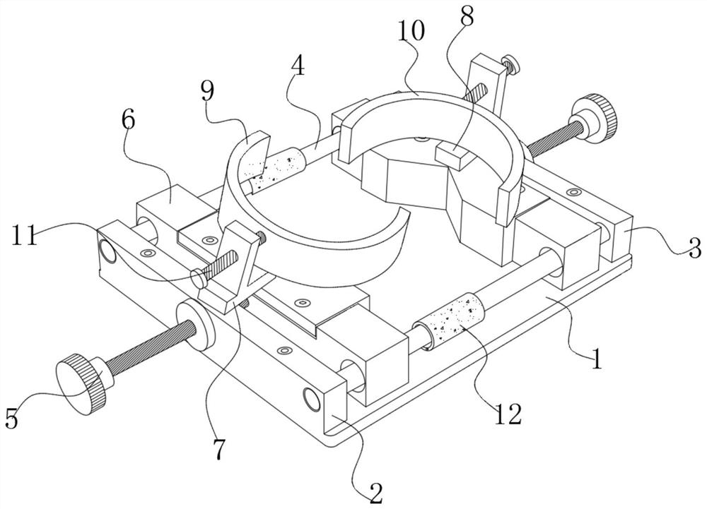
[0024] Such as Figure 1 to Figure 4 As shown, the present invention includes an underframe, and the underframe includes a base plate 1, a first base 2 and a third base 3, and the left and right sides of the upper surface of the base plate 1 are symmetrically fixed with the first base 2 and the second base 3, The central positions of the first base 2 and the second base 3 are respectively connected with a first threaded rod 5 placed horizontally, and the ends of the first threaded rod 5 extend into the sliding seat 6, and the two sliding seats 6 are close to each other. One end is V-shaped. Such as figure 1 As shown, the left and right sides of the first base 2 and the second base 3 are respectively connected with a guide rod 4, the guide rod 4 passes through the sliding seat 6, and the guide rod 4 between the two sliding seats 6 is also connected to the guide rod 4. Cov...


PUM


Abstract

The invention discloses a clamping device for machining a reeling device. The clamping device comprises a bottom frame, each of the left side and the right side of the bottom frame is connected with afirst threaded rod, the tail ends of the first threaded rods extend into a sliding seat, a fixed bin is fixed to the sliding seat located on one side of the bottom frame, a first semicircular ring isarranged at the top of the fixed bin, a fixed seat is installed at the top of the bottom frame located on the other side, a second semicircular ring is arranged at the top of the fixed seat, third bases are fixed to the top of the fixed bin and the top of the fixed seat, second threaded rods are connected into the third bases, the tail ends of the second threaded rods stretch into the first semicircular ring and the second semicircular ring correspondingly, and a piston plate is arranged in the fixed bin, the piston plate is connected with the second threaded rods above the fixed bin, a plurality of buffer clamping assemblies are correspondingly arranged in the first semicircular ring and the second semicircular ring, and an ejecting device is further arranged in the first semicircular ring and connected with the fixed bin. According to the clamping device, the overall clamping efficiency can be improved, and vibration of the reeling device is reduced.

Description

technical field [0001] The invention relates to a clamping device, in particular to a clamping device for processing a winder. Background technique [0002] The strength curler is an uncommon exercise equipment, but it can achieve the same exercise effect as other equipment if it is used reasonably. In addition, it is a special tool for developing the forearm muscles, and it is also very effective in enhancing grip strength. So it can be said that it is a neglected fitness equipment. There are two commonly used force coilers, namely: hand-held force coiler and bracket type force coiler, both of which are combined with a stick body and a rope body, and a clamping device is required for auxiliary fixation when processing the force coiler Processing, then punching and threading. [0003] Due to the existing clamping device for processing the force coiler, only one end of the force coiler is usually clamped for processing, and the force coiler is easy to vibrate during process...

Claims


Application Information

Patent Timeline
IPC IPC(8): B25B11/00
CPCB25B11/00
Inventor 罗勇
Owner NANJING COLLEGE OF INFORMATION TECH
Features
  • R&D
  • Intellectual Property
  • Life Sciences
  • Materials
  • Tech Scout
  • Unparalleled Data Quality
  • Higher Quality Content
  • 60% Fewer Hallucinations
Learn More