Non-fixed-point type charging pile for underground garage

A technology for underground garages and charging piles, which is applied to electric vehicle charging technology, charging stations, electric vehicles, etc. It can solve the problems of heavy cables, occupying land space, and difficulty in manual handling and winding, so as to reduce the occupied area of ​​the ground and reduce the Labor intensity, the effect of reducing the number of laying

Inactive Publication Date: 2020-09-11
周立
View PDF0 Cites 3 Cited by
  • Summary
  • Abstract
  • Description
  • Claims
  • Application Information

AI Technical Summary

Problems solved by technology

[0004] The purpose of the present invention is to provide a non-fixed-point charging pile for underground garages to solve the problem that the current charging piles proposed in the background technology are usually completely fixed on the parking spaces, but the cost of laying the charging piles is high, and it is difficult to install them on each parking space. The charging piles are all installed. The actual survey found that the underground garages are usually allocated and installed charging piles by partition. However, the proportion of electric vehicles and fuel vehicles changes year by year, making the original charging piles unable to meet the demand. More charging piles are often needed. Existing The charging piles are usually installed directly on the ground, occupying a large amount of land space, reducing the parking area of ​​the underground garage and increasing the cost of use. In addition, the existing charging piles need to manually rewind the cables, and the cables used in the charging piles are added The quality of the charging gun is relatively large, it is difficult to carry and rewind manually, and it is very inconvenient to use

Method used


Image

  • Non-fixed-point type charging pile for underground garage
  • Non-fixed-point type charging pile for underground garage
  • Non-fixed-point type charging pile for underground garage

Examples


Embodiment Construction

[0037] The following will clearly and completely describe the technical solutions in the embodiments of the present invention with reference to the accompanying drawings in the embodiments of the present invention. Obviously, the described embodiments are only some, not all, embodiments of the present invention. Based on the embodiments of the present invention, all other embodiments obtained by persons of ordinary skill in the art without making creative efforts belong to the protection scope of the present invention.

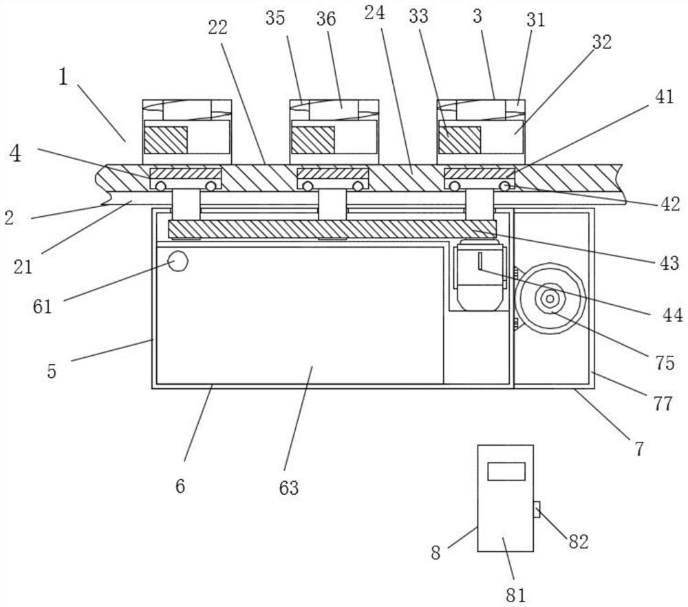
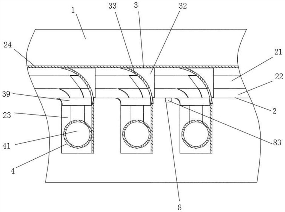
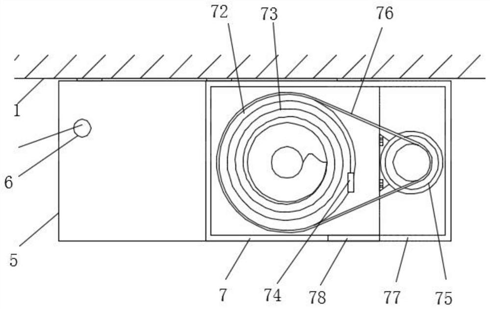
[0038] see Figure 1-7 , the present invention provides a technical solution: a non-fixed-point charging pile for an underground garage, such as figure 1 , figure 2 with Figure 4As shown, a travel track 2 is provided at the bottom of the top base 1, and a reversing device 3 is arranged inside the top base 1. At the same time, the reversing device 3 communicates with the travel track 2, and a moving mechanism 4 is arranged inside the travel track 2, and the...


PUM


Abstract

The invention discloses a non-fixed-point type charging pile for an underground garage. The charging pile comprises a top seat, an advancing track is arranged at the bottom of the top seat; a reversing device is arranged in the top seat and communicates with the advancing track, a moving mechanism is arranged in the advancing track, the lower end of the moving mechanism is arranged in the shell, an inserting structure is arranged on the left side in the shell, a hoisting mechanism is arranged on the right side in the shell, and a control mechanism is arranged at the bottom of the shell. In thenon-fixed-point charging pile for an underground garage, a reversing device, an advancing track and a moving mechanism are arranged. The first compression spring pushes the turning guide block to beembedded into the main rail; the rotating direction of the gear is changed, so that the gear moves into the auxiliary rail through the second rack, the shell accurately moves to the position above thedesignated parking space, components in the shell are electrically connected with an external power source to complete charging of the electric vehicle, the laying number of charging piles is reduced, meanwhile, the number of the charging piles can be increased or decreased at any time, and use is more practical.

Description

technical field [0001] The invention relates to the technical field of charging piles, in particular to a non-fixed-point charging pile for underground garages. Background technique [0002] With the development of technology and the strengthening of people's awareness of environmental protection, the proportion of electric vehicles in vehicles is getting higher and higher, so a large number of supporting charging piles are needed. [0003] The current charging piles are usually completely fixed on the parking spaces, but the cost of laying the charging piles is high, and it is difficult to install charging piles in every parking space. The actual investigation found that underground garages are usually allocated and installed charging piles in partitions, but electric vehicles and fuel The proportion of car ownership changes year by year, which makes the original charging piles unable to meet the demand. It is often necessary to add charging piles. The existing charging pil...

Claims


Application Information

Patent Timeline
Patent Type & Authority Applications(China)
IPC IPC(8): B60L53/31B60L53/18B65H75/38B65H75/44
CPCB65H75/38B65H75/4486B65H2701/34B60L53/18B60L53/31Y02T10/70Y02T10/7072Y02T90/12Y02T90/14
Inventor 周立
Owner 周立
Why Eureka
Try Eureka