Nested bolt fastener easy to remove

A bolt fastener and nesting technology, applied in the direction of threaded fasteners, nuts, connecting components, etc., can solve the problems of fasteners that are not easy to disassemble, difficult to install, and complicated to disassemble, so as to improve the fastening effect and easy to install. , to avoid the effect of thread meshing and slipping

Active Publication Date: 2020-09-11
嘉善伟悦紧固件有限公司
8 Cites 1 Cited by

AI-Extracted Technical Summary

Problems solved by technology

[0004] The purpose of the present invention is to provide a nested bolt fastener that is easy to disassemble, so as to solve the problem that the general nuts and bolts in the background technology are engaged through threads, which is easy to slip during installation, and the bolts need to...

Method used

Please refer to Fig. 1-6, the present invention provides a kind of technical scheme: a kind of nested bolt fastener that is convenient to disassemble, comprises bolt 1, and bolt 1 is contacted and connected with lower screw sleeve 2, the lower screw sleeve 2 One end is fixedly connected with an extension part 3, and the extension part 3 is hinged at one end of the upper screw sleeve 4. There are cavities respectively in the upper screw sleeve 4 and the lower screw sleeve 2, and the upper screw sleeve 4 and the lower screw sleeve 2 are respectively rotated. Connected with a rotating shaft 5, the other end of the rotating shaft 5 extends into the cavity, and the extending end of the rotatin...

Abstract

The invention discloses a nested bolt fastener easy to remove. The nested bolt fastener comprises a bolt, and the bolt is in contact connection with a lower thread sleeve; one end of the lower threadsleeve is fixedly connected with an extension part, and the extension part is hinged to one end of an upper thread sleeve; the upper thread sleeve and the lower thread sleeve are each provided with acavity internally, and sleeved with a rotating shaft separately and rotatably; the other end of the rotating shaft extends into the cavities, and the extension end of the rotating shaft is fixedly connected with a rotating rod; the other end of the rotating rod is rotatably connected with a sliding block, and the other end of the sliding block is slidably sleeved in a sliding sleeve; and the sidewall of the sliding block is fixedly connected with a guide rod. According to the nested bolt fastener easy to remove, a clamping part can be secured, so that the clamping part is engaged with a fixing bolt; bidirectional operation for the bolt is not required, and the installation is easy; the thread engagement slip is avoided, and the fastening effect is improved; the fastener is easy to remove,and manual rotation of the bolt is not required; and the working efficiency is improved, and damage to components is avoided.

Application Domain

Technology Topic

Image

  • Nested bolt fastener easy to remove
  • Nested bolt fastener easy to remove
  • Nested bolt fastener easy to remove

Examples

  • Experimental program(1)

Example Embodiment

[0023] The technical solutions in the embodiments of the present invention will be clearly and completely described below in conjunction with the accompanying drawings in the embodiments of the present invention. Obviously, the described embodiments are only a part of the embodiments of the present invention, rather than all the embodiments. Based on the embodiments of the present invention, all other embodiments obtained by those of ordinary skill in the art without creative work shall fall within the protection scope of the present invention.
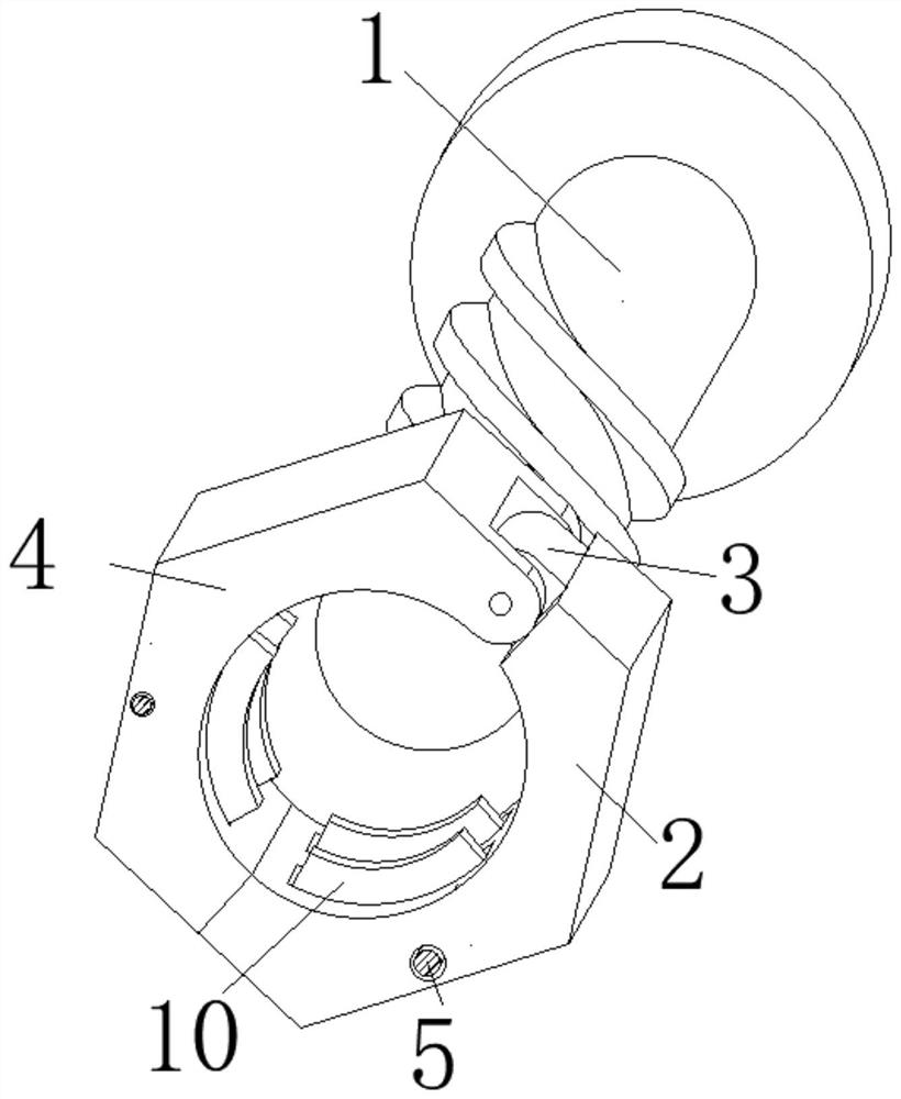
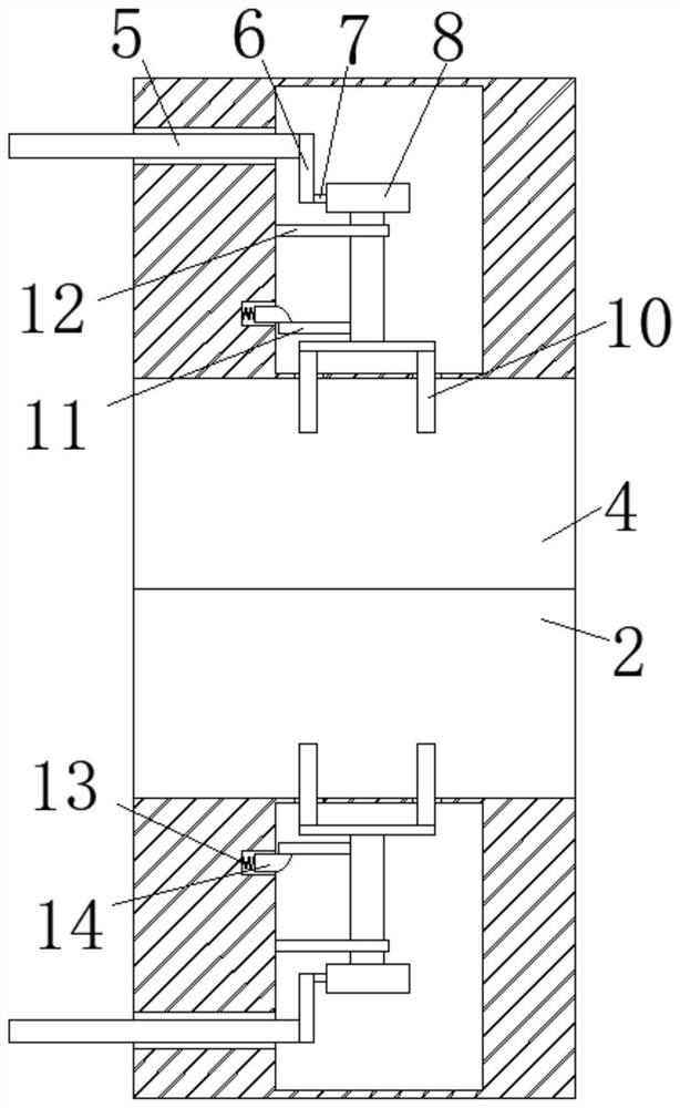
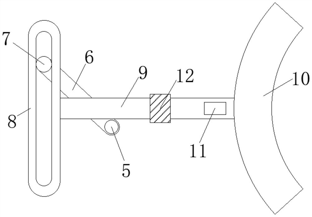
[0024] See Figure 1-6 , The present invention provides a technical solution: a nested bolt fastener that is easy to disassemble, comprising a bolt 1, a lower threaded sleeve 2 is contacted and connected to the bolt 1, and an extension 3 is fixed at one end of the lower threaded sleeve 2 to extend The part 3 is hingedly connected to one end of the upper threaded sleeve 4, the upper threaded sleeve 4 and the lower threaded sleeve 2 are respectively provided with cavities, and the upper threaded sleeve 4 and the lower threaded sleeve 2 are respectively connected with a rotating shaft 5, the other of the rotating shaft 5 One end extends into the cavity, and a rotating rod 6 is fixedly connected to the extending end of the rotating shaft 5, the other end of the rotating rod 6 is rotatably connected with a slider 7, and the other end of the slider 7 is slidingly sleeved in the sliding sleeve 8. A guide rod 9 is fixedly connected to the side wall of the sliding sleeve 8, a clamp 10 is installed at the other end of the guide rod 9, and a blocking rod 11 is fixed to the side wall of the guide rod 9, to achieve the purpose of stabilizing the clamp 10. Make the clip 10 engage with the fixing bolt 1, no need to perform two-way operation on the bolt 1, easy to install, also avoid thread engagement slippage, improve the fastening effect;
[0025] The bottom end of the upper threaded sleeve 4 is provided with a groove one, and the bottom end of the lower threaded sleeve 2 is provided with a connecting block 15 which is fitted and connected with the groove one, and the connecting block 15 and the groove one are respectively There are semi-circular slide grooves for opening and closing. The bottom surfaces of the semi-circular slide grooves are respectively installed with spring two 16; the other end of spring two 16 is respectively fixedly connected with rotor one 17 and rotor two 18, and the bottom surface of rotor two 18 is hinged. There is a pull rod 19, the other end of the pull rod 19 extends outside the connecting block 15, and the pull rod 19 outside the upper screw sleeve 4 is pulled, so that the pull rod 19 pulls the rotating block two 18 to rotate, and the rotating block two 18 pushes the rotating block 17 to rotate, making the rotation Block two 18 and rotating block one 17 are horizontal, so that the fixing of connecting block one 15 and the upper screw sleeve 4 is released, and then the spring two 16 on the bottom surface of rotating block two 18 and rotating block one 17 is pressed, which is the two rotating block 18 and the rotating block The reset of a 17 provides thrust to prepare for the re-fixation of the lower screw sleeve 2 and the upper screw sleeve 4 after they are separated, to achieve the purpose of releasing the internal fixation of the lower screw sleeve 2 and the upper screw sleeve 4, making the fasteners easy to remove without Manually rotate the bolt 1 to improve work efficiency and avoid component damage; the side walls of the lower screw sleeve 2 and the upper screw sleeve 4 are respectively installed with a limit frame 20 and a connecting block 22, and the other end of the limit frame 20 is sleeved in In the positioning rod 21, the other end of the positioning rod 21 is fixedly connected with a guide post 23, and a stop rod 24 is installed on the side wall of the guide post 23, so that the push rod 27 squeezes the second block 26, thereby causing the second block 26 to squeeze Press the spring three 25 to disengage the second block 26 from the second stop rod 24, thereby making the guide post 23 on the second stop rod 24 moveable, and rotate the positioning rod 21 so that the guide post 23 is separated from the second connecting block 22, and the push The lever 27 makes the block two 26 reset under the rebound of the spring three 25 to prepare for re-fixing. When the positioning lever 21 rotates, the restraint of the limit frame 20 on the spring four 28 is released, so that the limit frame 20 and The positioning rod 21 is disengaged to achieve the purpose of releasing the external fixation of the lower screw sleeve 2 and the upper screw sleeve 4; the inner walls of the lower screw sleeve 2 and the upper screw sleeve 4 are respectively provided with a slideway 1 through the cavity, a slideway 1 and a clamping piece 10 is connected by sliding, and groove two is opened on the side wall of the cavity, and spring one 13 is installed on the side wall of groove two. The other end of spring one 13 is fixedly connected with a clamping block 14, and the other of clamping block 14. One end is in contact with the stop rod 11, and the block 14 is slidably connected to the groove 2, so that the structure is reasonable and it is convenient to fix the stop rod 11; the guide rod 9 is slidingly sleeved with the limit sleeve 12, and the limit sleeve 12 is connected to the hollow The side walls of cavity one are fixed, two clamping pieces 10 are arranged in parallel, and the two clamping pieces 10 are arranged obliquely with the bolt 1, which improves the fixing effect of the bolt 1 and is convenient to achieve the expected effect; rotary block 1 17 and rotary block 2 18 is slidably connected to the semicircular chute, and the tie rod 19 is slidably connected to the upper screw sleeve 4, making the structure reasonable and easy to achieve the desired effect; the positioning rod 21 is hinged with the side wall of the upper screw sleeve 4, and the limit frame 20 is connected to the lower screw sleeve 4. A spring 29 28 is installed between the sleeves 2 to facilitate the limit frame 20 to be separated from the positioning rod 21; the connecting block 22 is provided with a slideway two, and the side wall of the slideway two is provided with groove three and the side wall of the groove three There is a spring three 25, spring The other end of the third 25 is fixedly connected to the second block 26, the second block 26 is in contact with the second stop rod 24, and the second block 26 is fixedly connected with a push rod 27, and the other end of the push rod 27 extends to the second connecting block 22 In addition, the structure is reasonable and it is convenient to achieve the expected effect.
[0026] Working principle: By placing the bolt 1 in the through hole, placing the lower threaded sleeve 2 on the side wall of the bolt 1, the extension 3 makes the upper threaded sleeve 4 rotate, thereby closing the lower threaded sleeve 2 and the upper threaded sleeve 4 , To achieve the purpose of the lower screw sleeve 2 and the upper screw sleeve 4 to sleeve the bolt 1, and then rotate the shaft 5 on the lower screw sleeve 2 and the upper screw sleeve 4, so that the shaft 5 drives the rotating rod 6 in the cavity to rotate, thereby making the rotation The sliding block 7 on the rod 6 pushes the sliding sleeve 8 to move, and the guide rod 9 on the sliding sleeve 8 is restricted and guided by the limit sleeve 12, so that the sliding sleeve 8 and the guide rod 9 can only move in a straight line, thereby making the guide rod The clamp 10 on 9 is fitted with the bolt 1, and at the same time, the blocking rod 11 on the guide rod 9 squeezes the blocking block 14 in the groove 2, so that the clamping block 14 shrinks, and the spring 13 is compressed. When 11 passes through the block 14, the restraint on the spring 13 is released, so that the spring 13 pushes the block 14 to the limit stop bar 11 to achieve the purpose of stabilizing the clamping member 10 so that the clamping member 10 engages the fixing bolt 1, without The two-way operation of the bolt 1 is easy to install, and also avoids thread engagement and slippage, which improves the fastening effect. When it is necessary to disassemble, press the push rod 27 on the second connecting block 22 to make the push rod 27 squeeze the second block 26. In turn, the second block 26 squeezes the spring three 25, so that the second block 26 is separated from the second stop rod 24, so that the guide post 23 on the second stop rod 24 can be moved, and the positioning rod 21 is rotated so that the guide post 23 is removed from the connecting block Disengage within the second 22, loosen the push rod 27, so that the block two 26 is reset under the rebound of the spring three 25 to prepare for re-fixing, and when the positioning rod 21 rotates, the restraint of the limit frame 20 on the spring four 28 is released , The limit frame 20 is separated from the positioning rod 21 to achieve the purpose of releasing the external fixation of the lower screw sleeve 2 and the upper screw sleeve 4. At the same time, the pull rod 19 outside the upper screw sleeve 4 is pulled, so that the pull rod 19 pulls the rotating block 18 to rotate. Block two 18 pushes rotating block one 17 to rotate so that rotating block two 18 and rotating block one 17 are level, thereby releasing the fixing of connecting block one 15 and upper screw sleeve 4, and then squeezing the bottom surface of rotating block two 18 and rotating block one 17. The second spring 16 provides thrust for the return of the second 18 and the first 17 rotors, so as to prepare for the re-fixation of the lower screw sleeve 2 and the upper screw sleeve 4 after they are separated, so as to release the inside of the lower screw sleeve 2 and the upper screw sleeve 4 The purpose of fixing is to make the fasteners easy to remove without manually rotating the bolt 1, which improves work efficiency, avoids component damage, and completes the operation.
[0027] Although the embodiments of the present invention have been shown and described, those of ordinary skill in the art can understand that various changes, modifications, and substitutions can be made to these embodiments without departing from the principle and spirit of the present invention. And variations, the scope of the present invention is defined by the appended claims and their equivalents.

PUM

no PUM

Description & Claims & Application Information

We can also present the details of the Description, Claims and Application information to help users get a comprehensive understanding of the technical details of the patent, such as background art, summary of invention, brief description of drawings, description of embodiments, and other original content. On the other hand, users can also determine the specific scope of protection of the technology through the list of claims; as well as understand the changes in the life cycle of the technology with the presentation of the patent timeline. Login to view more.

Similar technology patents

Classification and recommendation of technical efficacy words

Why Eureka
Try Eureka