

Light-emitting diode (LED) tiled screen module box
A splicing screen and LED light source technology, which is applied in the direction of cabinet/cabinet/drawer components, instruments, identification devices, etc., can solve problems such as heavy workload, affecting display effect, and increased gap between splicing screen modules. Achieve quick and easy installation, avoid frequent maintenance, and prolong stable use
- Summary
- Abstract
- Description
- Claims
- Application Information
AI Technical Summary
Problems solved by technology
Method used
Image

Examples
Embodiment Construction
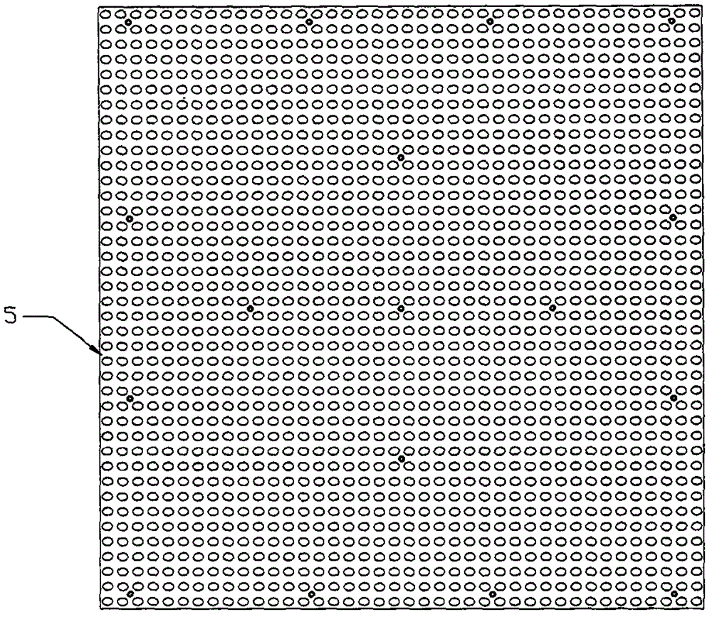
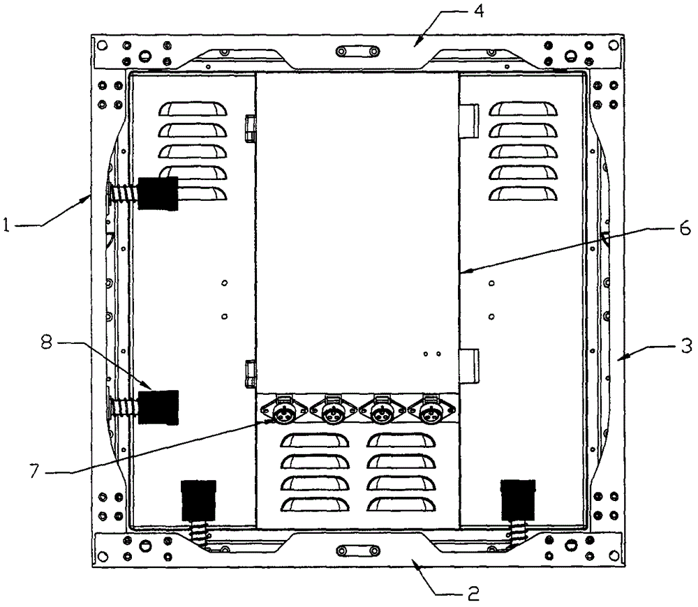
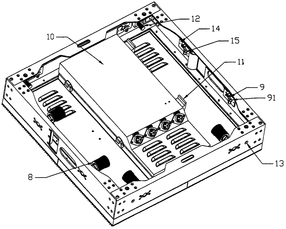
[0015] This embodiment includes a square module frame composed of four profile frames: the first profile frame 1, the second profile frame 2, the third profile frame 3 and the fourth profile frame 4, and the front of the module frame is provided with a dot matrix arrangement The LED light source 5 of the LED light source 5 is provided with a module power supply box 6 with a power supply and a circuit board installed on the back of the LED light source 5 inside the module frame, and a connection terminal 7 is provided outside the power supply box 6. The two perpendicular The first profile frame 1 and the second profile frame 2 are provided with at least two quick locking levers 8, and the other two perpendicular third profile frames 3 and fourth profile frame 4 are provided with lock holes corresponding to the positions of the quick locking levers 9. Described fast lock bar 8 comprises a lock bar 81, and one end of lock bar 8 is provided with the pin 82 that passes through a pe...
PUM
 Abstract
Description
Claims
Application Information