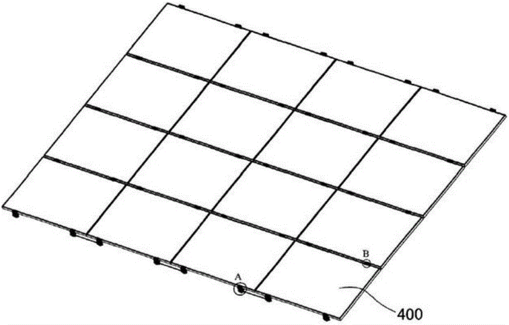
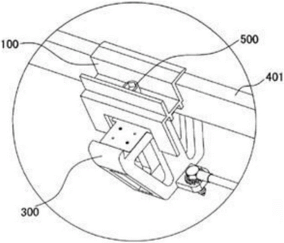
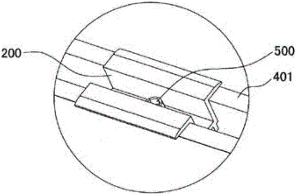
[0028] Such as figure 1 , 2 As shown in 3, a roof photovoltaic module support includes a solar photovoltaic module 400, a roof fixing member 300, a side card 100 and an intermediate card 200.
[0029] Such as Figure 4 with 5 Shown is a schematic diagram of the structure of the roof fixture. The roof fixing member 300 includes a connecting member 1, a supporting member 2, a fixing member 3, a clamping groove 4, a screw hole 5 and a through hole 6; the supporting member 2 is arranged at the top end of the connecting member 1, and the fixing member 3 is arranged at the bottom end of the connecting member 1. Two sides of the supporting member 2 are symmetrically provided with clamping grooves 4, a screw hole 5 is provided in the middle of the supporting member 2, and a through hole 6 is provided on the fixing member 3.
[0030] The outer surface of the clamping groove of the supporting member of the roof fixing member is inclined inward, and the included angle a with the horizontal plane is 30°-90°. This structure can better clamp and fix the solar photovoltaic module in the clamping groove, prevent the module from slipping out due to vibration and other reasons, and can effectively avoid the shaking of the module.
[0031] Such as Image 6 , 7 , 8 and 9 show the structure diagram of the side card. The side card 100 includes a side card connector 11, a side card support 12, a side card support plate 13, a side card connection hole 14 and a clamping groove 15; the side card support 12 is arranged on one side of the side card connector 11, In an inverted L shape, the side card support plate 13 is provided on the other side of the side card connector 11, the side card connector 11 is also provided with a side card connection hole 14, and the bottom of the side card support plate 13 is provided with a clamping groove 15. The side card is an integrated structure; the side card 100 is arranged on the side of the solar photovoltaic module 400, the upper part of the frame of the solar photovoltaic module 400 is attached to the side card support 12, and the bottom of the frame is clamped to the clamp of the support of the roof fixing member In the slot 4, the side clip connection hole 14 and the screw hole 5 of the support member of the roof fixing member are fixedly connected by bolts 500 so that the frame of the solar photovoltaic module 400 is clamped between the side clip 100 and the roof fixing member 300.
[0032] Both the bottom surface and the top surface of the side card connector of the side card are provided with side card reinforcement ribs, and the contact surface of the side card support member of the side card which is attached to the frame of the solar photovoltaic module is provided with a non-slip structure.
[0033] Such as Picture 10 , 11 , 12 and 13 show the structure diagram of the intermediate card. The mezzanine card 200 includes a mezzanine card connector 21, a mezzanine card support 22, and a mezzanine card connecting hole 23; the mezzanine card 200 has a left-right symmetrical structure, with a middle card connector 21 in the middle, and an inverted L-shaped mezzanine card support on one side The middle card connector 21 is also provided with a middle card connection hole 23; the middle card 200 is arranged between the two solar photovoltaic modules 400, the upper part of the solar photovoltaic module 400 is attached to the middle card support 22, and the bottom of the frame Clamped in the clamping slot 4 of the support of the roof fixing member 300, the middle card connecting hole 14 and the screw hole 5 of the support member of the roof fixing member 300 are fixedly connected by bolts, so that the frame of the solar photovoltaic module 400 is clamped to the middle card 200 Between the roof fixing member 300 and the roof fixing member 300, the roof fixing member 300 is fixed on the roof through the through hole 6 on the fixing member.
[0034] The intermediate card connecting hole 23 of the intermediate card is arranged in the center of the intermediate card connecting piece 21, the bottom surface of the intermediate card connecting piece 21 is also provided with an intermediate card reinforcing rib 24, and the intermediate card supporting piece 22 is attached to the contact surface of the solar photovoltaic module frame A non-slip structure 17 is provided.
[0035] The clamping groove of the support of the roof fixing member should be matched with the aluminum frame of the solar photovoltaic module to clamp and fix the solar photovoltaic module in the clamping groove. For the roof fixings set on the side, generally only one side of the clamping slot is used and used in conjunction with the side clip; for the roof fixings set in the middle of two adjacent components, the clamps on both sides The slots are used to clamp the two components on both sides, and are used in conjunction with the middle card. The middle part of the support is provided with a screw hole, which is used for screw connection with the side card or the middle card, so that the solar photovoltaic module is clamped and fixed between the side card or the middle card and the roof fixing member. The roof fixing part is an integral structure, which can be made by drawing aluminum profiles or by opening moulds. The through hole of the fixing piece is used with self-tapping drill bolts to fix the whole roof fixing piece on the roof. In order to facilitate the actual installation, the fixing piece and the supporting piece are arranged in a crisscross pattern. There are two fixing pieces, which are symmetrically arranged on both sides of the connecting piece and arranged in a crisscross pattern with the supporting piece.
[0036] The connecting piece of the roof fixing piece is a hollow structure, and the hollow structure is preferably a left-right symmetrical structure, which reduces the bearing capacity of the roof and saves material costs on the premise of ensuring the strength.
[0037] The installation method between the roof photovoltaic modules is as follows: when installing, start from one side, first clamp the side card connection hole of the side card and the screw hole of the roof fixing part through the bolts, and then connect one side of the solar photovoltaic module frame The upper part of the side is pressed against the inverted L-shaped support of the side clip, and the bottom of the frame is clamped in the clamping groove of the support of the roof fixing part, and then the bolts are matched and locked to fix the roof fixing part on the roof to complete the side For the installation of the position, refer to the above method for other installation positions, and complete the installation of the solar photovoltaic modules on the side;
[0038] After installing the solar photovoltaic module on the side, install the roof fixing piece and the middle card on the other side of the module, and clamp the bottom of the frame on the other side of the module into the clamping groove of the roof fixing piece, and then install it above it The middle card completes the installation of the first photovoltaic module; after installing the first photovoltaic module, fix the roof fixing piece on the other side of the first solar photovoltaic module to the roof, and then insert the second solar photovoltaic module into the roof In the fixing piece and the middle card, install the roof fixing piece on the other side of the second solar photovoltaic module at the same time, and fix it on the roof, tighten the middle card pressed on the first and second solar photovoltaic modules, Complete the installation of the second module, and also complete the installation of a row of modules, thus completing the installation of the rooftop photovoltaic power generation system.
[0039] Although the present invention is illustrated and described in terms of preferred embodiments, those skilled in the art should understand that various changes and modifications can be made to the present invention as long as it does not exceed the scope defined by the claims of the present invention.