
A diaphragm precision cutting positioning device and using method

A positioning device and diaphragm technology, applied in metal processing and other directions, can solve the problems of increasing the placement stability of the diaphragm body, and achieve the effect of rapid installation and increased stability

Active Publication Date: 2021-07-13
四川省绵阳市鸿永盛模塑有限公司
View PDF5 Cites 0 Cited by
  • Summary
  • Abstract
  • Description
  • Claims
  • Application Information

AI Technical Summary

Problems solved by technology

[0006] The purpose of the present invention is to provide a diaphragm precision cutting and positioning device and a method of use to solve the problem of increasing the stability of the diaphragm body placed in the above-mentioned background technology.

Method used


Image

  • A diaphragm precision cutting positioning device and using method
  • A diaphragm precision cutting positioning device and using method
  • A diaphragm precision cutting positioning device and using method

Examples


Embodiment Construction

[0025] The following will clearly and completely describe the technical solutions in the embodiments of the present invention with reference to the accompanying drawings in the embodiments of the present invention. Obviously, the described embodiments are only some, not all, embodiments of the present invention. Based on the embodiments of the present invention, all other embodiments obtained by persons of ordinary skill in the art without making creative efforts belong to the protection scope of the present invention.

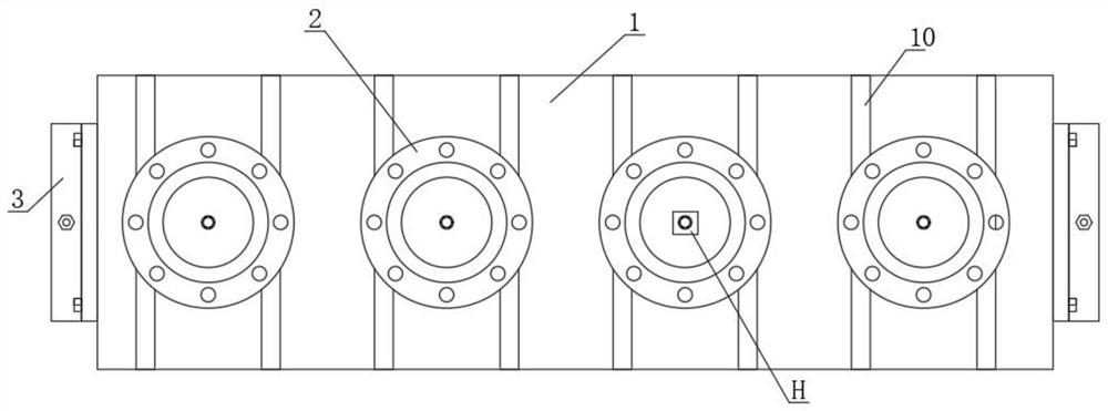
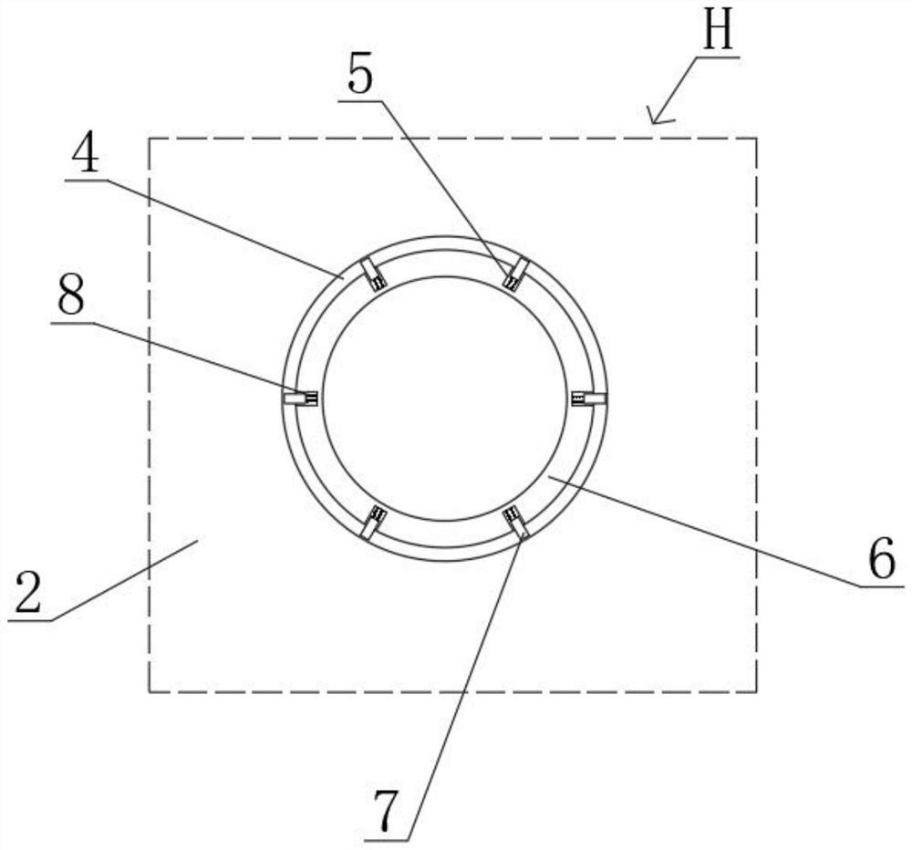
[0026] see figure 1 , figure 2 and image 3 , the present invention provides a technical solution: a diaphragm precision cutting and positioning device, including a workbench 1, a diaphragm body 2 and a stabilizing mechanism, the top of the workbench 1 is provided with a plurality of spaced spacing posts 6, the The surface of the body 2 is provided with a perforation 4, and the perforation 4 can be inserted into the limit post 6. The stabilizing mechanism i...


PUM


Abstract

The invention discloses a diaphragm precision cutting and positioning device, which comprises a workbench, a diaphragm body and a stabilizing mechanism. The top of the workbench is provided with a plurality of spacing posts distributed at intervals, and the surface of the diaphragm body is provided with Perforated, and the perforated hole can be inserted into the limit column. The stabilizing mechanism includes a groove, a block and a spring. There are multiple grooves on the surface of the limit post. One end of the block is embedded in the groove, and the other end extends out of the groove, and can Against the perforation, one end of the spring is connected to the embedded end face of the block, and the other end is connected to the groove bottom of the groove; the present invention also discloses a method for using a diaphragm precise cutting and positioning device. The beneficial effects of the present invention are: Through the designed stable mechanism, the diaphragm body is positioned while increasing the stability of the diaphragm body, which solves the traditional problem of unstable placement of the diaphragm body after positioning; through the designed installation mechanism, it is helpful to realize the work The quick installation of the table is also convenient to remove for maintenance when the surface of the work table is worn.

Description

technical field [0001] The invention belongs to the technical field of diaphragm precise cutting and positioning, and in particular relates to a diaphragm precise cutting and positioning device and also relates to a method for using the positioning device. Background technique [0002] Diaphragms are classified by industry: diaphragms in the electroacoustic industry; rubber diaphragms in the mechanical industry; microporous diaphragms in the filtration and isolation industry; diaphragms in the optical industry. [0003] When the diaphragm is finely cut, it is necessary to position the diaphragm to improve the efficiency of fine cutting. [0004] The deficiencies in the following aspects when the existing diaphragm precision cutting and positioning device is used: [0005] There are deficiencies in increasing the stability of the placement of the diaphragm body. Contents of the invention [0006] The object of the present invention is to provide a membrane fine-cutting an...

Claims


Application Information

Patent Timeline
Patent Type & Authority Patents(China)
IPC IPC(8): B26D7/01B26D7/20
CPCB26D7/015B26D7/20
Inventor 邹志伟
Owner 四川省绵阳市鸿永盛模塑有限公司
Learn More