Automatic winding device for cable manufacturing

A winding device and cable manufacturing technology, which is applied in the direction of transportation and packaging, thin material handling, and delivery of filamentous materials, etc., can solve the problems of loose cables, low cable tightness, and poor winding effects, and achieve winding Efficiency improvement, the effect of improving the winding effect

Active Publication Date: 2020-09-15
国网黑龙江省电力有限公司牡丹江供电公司 +1
View PDF13 Cites 2 Cited by
  • Summary
  • Abstract
  • Description
  • Claims
  • Application Information

AI Technical Summary

Problems solved by technology

Although the device can be used to wind the cable, the tightness of the cable is low during the winding process, and the cable is prone to loosening, resulting in poor winding effect. Therefore, an automatic winding for cable manufacturing is now provided. device to solve the above technical problems

Method used


Image

  • Automatic winding device for cable manufacturing
  • Automatic winding device for cable manufacturing
  • Automatic winding device for cable manufacturing

Examples


Embodiment 1

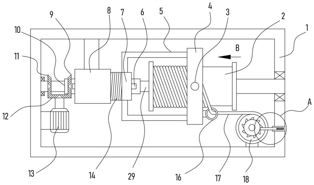
[0022] see Figure 1-4 , an automatic winding device for cable manufacturing, comprising a support frame 1, a drive motor 13 is fixed on the support frame 1, and the support frame 1 is rotatably equipped with a placement roller 18 for laying cables 17, and the support frame 1 rotates A winding roller 2 for winding the cable 17 is installed, the winding roller 2 is sleeved with a ring frame 4, the ring frame 4 is fixed with a limit ring 16 for the cable 17 to pass through, and the ring frame 4 is provided with a rolling mechanism for rolling the cable 17. A driving shaft 29 is coaxially fixed on the winding roller 2, and a translation mechanism for driving the translation of the ring frame 4 is connected to the driving shaft 29. The output shaft of the driving motor 13 is driven and connected with a rotating mechanism for driving the ring frame 4 to rotate relative to the winding roller 2, and the placing roller 18 is provided with a one-way positioning mechanism.

[0023] The...

Embodiment 2

[0029] On the basis of Embodiment 1, in addition, this device is also provided with a rotating mechanism, including a bevel gear III12 coaxially fixed with the output shaft of the drive motor 13, and the bevel gear III12 is meshed and connected with respectively sleeved and fixed on the drive shaft 29. And bevel gear II11 and bevel gear I9 on the rotary tube 10.

[0030] The drive motor 13 is used to drive the bevel gear III12 to rotate, and the bevel gear III12 simultaneously drives the bevel gear II11 and the bevel gear I9 meshed with it to rotate, thereby realizing the reverse rotation of the drive shaft 29 and the rotating tube 10. The winding roller 2 realizes reverse rotation, that is, the winding efficiency of the cable 17 by the winding roller 2 is significantly improved, and the rolling efficiency of the cable 17 by the rolling mechanism is significantly improved.

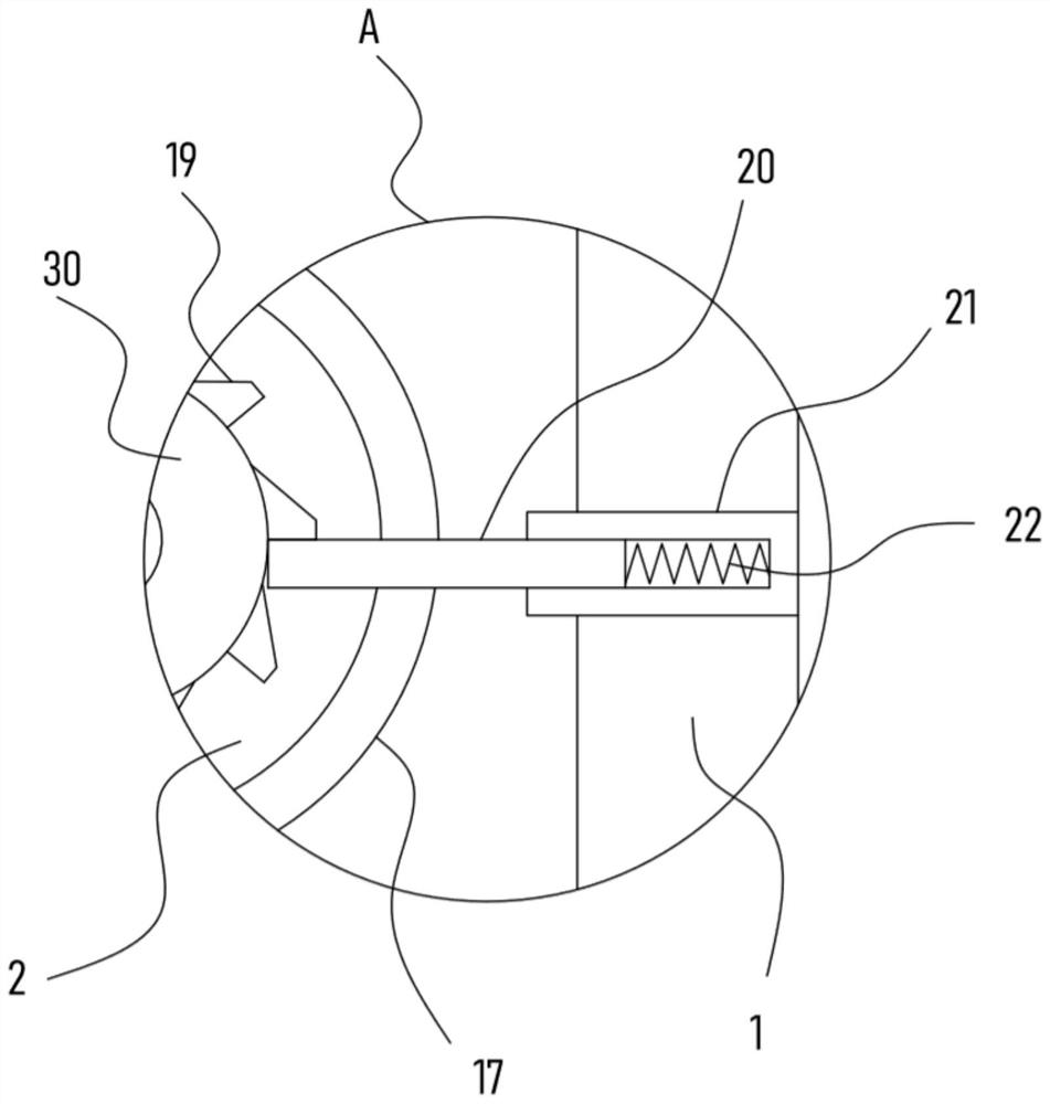
[0031] Further, the one-way positioning mechanism of the device includes a running wheel 30 coaxially f...


PUM


Abstract

The invention discloses an automatic winding device for cable manufacturing, and relates to the technical field of cable winding. The device comprises a supporting frame, wherein the supporting frameis rotatably provided with an unwinding roller for unwinding a cable, an annular frame is internally provided with a rolling mechanism for rolling the cable, a driving shaft is in transmission connection with a translation mechanism used for driving the annular frame to translate, an output shaft of a driving motor is in driving connection with a rotating mechanism used for driving the annular frame to rotate relative to a winding roller, and the unwinding roller is provided with a one-way positioning mechanism. According to the device, the annular frame can achieve a reverse rotation effect on the winding roller under the action of the rotating mechanism, the winding efficiency of the winding roller on the cable is remarkably improved, the annular frame can move transversely relative to the winding roller under driving of the translation mechanism, so that a limiting ring pulls the cable to be uniformly wound around the winding roller, the rolling mechanism of the annular frame performs step-by-step rolling action on the cable on the winding roller, the cable can be guaranteed to be tightly attached to the winding roller, and the cable winding effect is greatly improved.

Description

technical field [0001] The invention relates to the technical field of cable winding, in particular to an automatic winding device for cable manufacturing. Background technique [0002] Cables include power cables, control cables, compensation cables, shielded cables, high temperature cables, computer cables, signal cables, coaxial cables, fire-resistant cables, marine cables, mining cables, aluminum alloy cables, etc. Composed of multi-strand wires and insulating layers, they are used to connect circuits, electrical appliances, etc. Cables can be divided into DC cables and AC cables according to the photovoltaic power station system, and can be divided into DC cables and AC cables according to different uses and usage environments. [0003] The patent application publication No. CN109809256 A discloses a compression type cable winding equipment, including a base plate, a support frame is installed on both sides of the upper end of the base plate, a reciprocating screw rod i...

Claims


Application Information

Patent Timeline
IPC IPC(8): B65H54/44B65H54/28B65H54/52
CPCB65H54/44B65H54/2818B65H54/52B65H2701/34
Inventor 罗志诚
Owner 国网黑龙江省电力有限公司牡丹江供电公司
Why Eureka
Try Eureka