Construction method of industrial building shock absorption foundation

A construction method and technology for industrial buildings, applied in infrastructure engineering, construction, protection devices, etc., can solve the problems of continuous and severe vibration loads, subsidence, loss of support of industrial buildings, etc., to reduce liquefaction and improve supporting force. Effect

Active Publication Date: 2020-09-15
ZHEJIANG JINYU ENG CONSULTING CO LTD
View PDF6 Cites 2 Cited by
  • Summary
  • Abstract
  • Description
  • Claims
  • Application Information

AI Technical Summary

Problems solved by technology

[0002] In industrial buildings, heavy loads such as industrial equipment often have continuous and severe vibration loads. When acting on the foundation soil, its weight is borne by both the soil particles in the foundation and the pore water in the foundation. When the saturated soil is subjected to vibration loads Under the action, the soil particles in the foundation will appear due to the different sizes of the soil particles, and the displacement speed of the soil particles will be different. The soil particles that are originally closely connected to each other, under the vibration, there will always be a distance between them due to their respective subsidence displacement speeds. Not the same, sometimes the soil particles will jump up and down and leave each other in a suspended state. When the soil particles are connected, they have the effect of mutual force transmission. Once suspended, the force transmission effect will be lost. At this time, the vibration load of industrial equipment can not help but lose the force transmission effect. The soil particles are responsible for the pore water in the foundation. The water has no shear strength and has no ability to withstand vibration loads. Therefore, the uneven subsidence of the foundation soil after liquefaction causes industrial buildings to lose their support and cause large-scale subsidence.

Method used


Image

  • Construction method of industrial building shock absorption foundation
  • Construction method of industrial building shock absorption foundation
  • Construction method of industrial building shock absorption foundation

Examples


Embodiment Construction

[0014] The following will clearly and completely describe the technical solutions in the embodiments of the present invention with reference to the accompanying drawings in the embodiments of the present invention. Obviously, the described embodiments are only some, not all, embodiments of the present invention. Based on the embodiments of the present invention, all other embodiments obtained by persons of ordinary skill in the art without making creative efforts belong to the protection scope of the present invention.

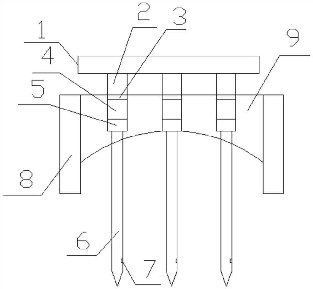
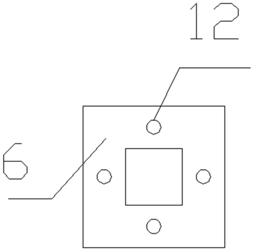
[0015] The embodiment of the invention discloses that the construction method of the shock-absorbing foundation of an industrial building includes a load-bearing frame 1, a support pier 2, a raft 9, and a support column 6. Concrete inverted beams 8 are arranged around the pier 2 and the raft 9, and the main reinforcement of the concrete inverted beams 8 adopts four steel bars with a diameter of 25 mm. The base of the raft 9 is made into an arch, and the concre...


PUM


Abstract

The invention discloses a construction method of an industrial building shock absorption foundation. The construction method is characterized by comprising the following construction steps of (1) mounting a hydraulic valve on a prefabricated support column, and then pressing the prefabricated support column into a soil body; (2) excavating the soil body to a designed bottom elevation, paving geotechnical cloth on an arch-shaped base, and enabling raft plate and concrete inverted beam formworks to adopt brick moulding beds; (3) binding steel bars of a raft plate and a concrete inverted beam, erecting the raft plate and concrete inverted beam formworks, and reserving shock absorption holes in the raft plate; (4) pouring concrete of the raft plate and the concrete inverted beam; (5) placing shock absorption blocks in the shock absorption holes, placing the shock absorption blocks on supporting columns, paving shock absorption materials on the shock absorption blocks, and paving steel plates on the shock absorption materials for sealing; (6) arranging buttresses on the steel plates at the shock absorption holes; (7) arranging a bearing frame on the buttresses; and (8) installing industrial equipment on the force bearing frame. The construction method is good in shock absorption effect.

Description

technical field [0001] The invention relates to the construction field, and more specifically relates to a construction method for shock-absorbing foundations of industrial buildings. Background technique [0002] In industrial buildings, heavy loads such as industrial equipment often have continuous and severe vibration loads. When acting on the foundation soil, its weight is borne by both the soil particles in the foundation and the pore water in the foundation. When the saturated soil is subjected to vibration loads Under the action, the soil particles in the foundation will appear due to the different sizes of the soil particles, and the displacement speed of the soil particles will be different. The soil particles that are originally closely connected to each other, under the vibration, there will always be a distance between them due to their respective subsidence displacement speeds. Not the same, sometimes the soil particles will jump up and down and leave each other...

Claims


Application Information

Patent Timeline
Patent Type & Authority Applications(China)
IPC IPC(8): E02D27/44E02D31/08
CPCE02D27/44E02D31/08
Inventor 范福东
Owner ZHEJIANG JINYU ENG CONSULTING CO LTD
Why Eureka
Try Eureka