A wooden chair installation hole gluing equipment
A technology for installing holes and wooden chairs, which is applied to devices and coatings that apply liquid to the surface, which can solve the problems of low gluing efficiency and cumbersome gluing operations back and forth, and achieve the effect of preventing glue precipitation.
- Summary
- Abstract
- Description
- Claims
- Application Information
AI Technical Summary
Problems solved by technology
Method used
Image
Examples
Embodiment 1
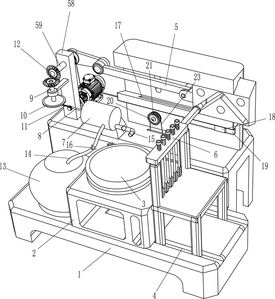
[0021] Such as Figure 1-4 As shown, a wooden chair installation hole gluing equipment includes a mounting table 1, a placing table 2, a loading basin 3, a guide rail 4, a reversing device 5 and a gluing mechanism 6, and the center of the front side of the top of the mounting table 1 is set There is a placing table 2, and a charging basin 3 is placed on the placing table 2, a guide track 4 for placing wooden chairs is embedded symmetrically in the front and rear of the top front side of the installation table 1, and a reversing device 5 is provided on the rear side of the top of the installation table 1 , The reversing device 5 is provided with a gluing mechanism 6 for gluing the mounting holes of the wooden chair.
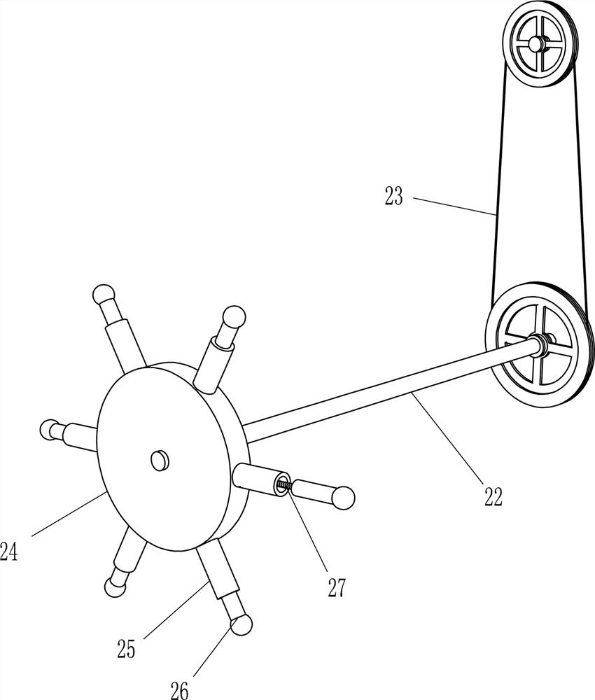
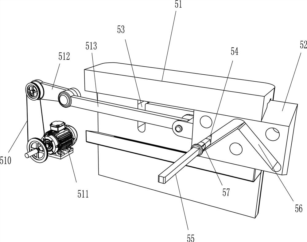
[0022] The reversing device 5 includes a slide rail 51, a sliding plate 52, a square slide block 54, a connecting rod 55, a round shaft sleeve 57, a mounting plate 58, a first rotating shaft 59, a first belt transmission mechanism 510, a servo motor 511, and a cra...
Embodiment 2
[0026] On the basis of Example 1, such as figure 1 and 4As shown, it also includes a cylinder 7, a piston rod 8, a second rotating shaft 9, a disc 10, a second connecting rod 11, a bevel gear 12, a plastic box 13, a feed pipe 14, a discharge pipe 15 and a one-way valve 16. A cylinder body 7 is arranged behind the left side of the top of the installation table 1, and a piston rod 8 is movable in the cylinder body 7. The front side of the installation plate 58 is vertically rotatably provided with a second rotating shaft 9, and the bottom end of the second rotating shaft 9 is arranged There is a disk 10, and the bottom of the disk 10 is eccentrically connected with a second connecting rod 11, which is rotatably connected with the piston rod 8, and the second rotating shaft 9 and the first rotating shaft 59 on the upper side are all provided with cones. The gear 12 and the two bevel gears 12 mesh with each other. There is a rubber box 13 on the left side of the top of the instal...
PUM
 Abstract
Description
Claims
Application Information
 - R&D
- Intellectual Property
- Life Sciences
- Materials
- Tech Scout
- Unparalleled Data Quality
- Higher Quality Content
- 60% Fewer Hallucinations
Browse by: Latest US Patents, China's latest patents, Technical Efficacy Thesaurus, Application Domain, Technology Topic, Popular Technical Reports.
© 2025 PatSnap. All rights reserved.Legal|Privacy policy|Modern Slavery Act Transparency Statement|Sitemap|About US| Contact US: help@patsnap.com


