
Method and device for monitoring electrode holder electrode wear state in resistance spot welding process

A wear state, resistance spot welding technology, applied in welding monitoring devices, resistance welding equipment, electrode maintenance, etc., can solve problems such as shortening the service life of the electrode of the welding tongs, working with the electrode of the welding tongs, affecting product quality, etc., to avoid problems such as The effect of working with illness, improving production efficiency and prolonging working life

Active Publication Date: 2020-09-18
ZHEJIANG GEELY AUTOMOBILE RES INST CO LTD +1
View PDF5 Cites 0 Cited by
  • Summary
  • Abstract
  • Description
  • Claims
  • Application Information

AI Technical Summary

Problems solved by technology

However, since this specified number of times is set based on past experience, this method will cause the following problems. During the grinding cycle of the welding tongs electrode, it is possible that the welding tongs electrode has reached the required number of welding times. In this way, the electrode of the welding tongs will work with a disease, which will affect the quality of the product. It is also possible that when the specified number of times of welding tongs is reached, the electrode of the welding tongs has not yet reached the state of needing to be repaired. Grinding, which will shorten the service life of the electrode of the welding gun and increase the production cost

Method used


Image

  • Method and device for monitoring electrode holder electrode wear state in resistance spot welding process
  • Method and device for monitoring electrode holder electrode wear state in resistance spot welding process

Examples


Embodiment Construction

[0025] In order to further illustrate the technical means and functions adopted by the present invention to achieve the intended invention purpose, the present invention will be described in detail below in conjunction with the accompanying drawings and preferred embodiments.

[0026] The invention provides a method and a monitoring device for monitoring the wear state of electrodes of resistance spot welding tongs. The method can accurately monitor the wear state of electrodes without stopping production, thereby improving production efficiency.

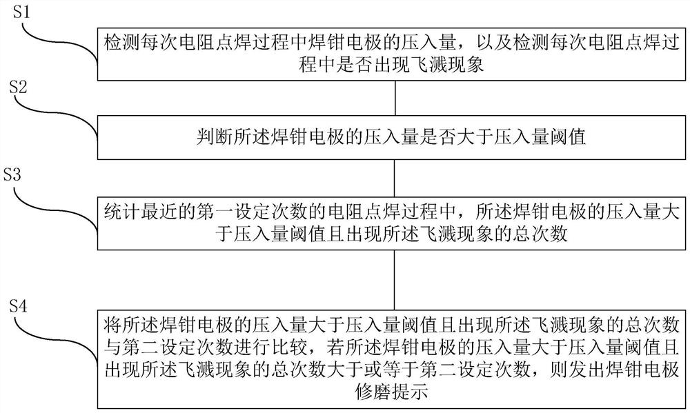
[0027] figure 1 Shown is the flow chart of the method for monitoring the electrode wear state of the resistance spot welding tongs provided by the embodiment of the present invention, as figure 1 As shown, the resistance spot welding gun electrode wear state detection method provided by the embodiment of the present invention includes the following steps:

[0028] S1: After the latest electrode grinding of the welding tongs, check ...


PUM


Abstract

The invention discloses a method and device for monitoring the electrode holder electrode wear state in the resistance spot welding process . The method comprises the following steps that S1, the press-in amount of an electrode holder electrode in each resistance spot welding process is detected, and whether the splashing phenomenon occurs or not in each resistance spot welding process is detected; S2, whether the press-in amount of the electrode holder electrode is larger than a press-in amount threshold value or not is judged; S3, the total number of times that the press-in amount of the electrode holder electrode is greater than the press-in amount threshold value and the splashing phenomenon occurs are counted in the last resistance spot welding process of the first set number of times; and S4, the total number of times that the press-in amount of the electrode holder electrode is larger than the press-in amount threshold value and the splashing phenomenon occurs are compared withsecond set number of times, and if the total number of times that the press-in amount of the electrode holder electrode is greater than the press-in amount threshold value and the splashing phenomenonoccurs are greater than or equal to the second set number of times, an electrode holder electrode grinding prompt is given out. According to the method, the wear state of the electrode can be accurately monitored under the condition that production does not need to be stopped, and the production efficiency is improved.

Description

technical field [0001] The invention relates to the technical field of vehicle manufacturing, in particular to a method and a monitoring device for monitoring the wear state of electrodes of resistance spot welding tongs. Background technique [0002] In the process of resistance spot welding of body-in-white, after a certain number of welding spots are welded, a certain amount of oxide will be formed on the electrode surface of the electrode cap, which will seriously affect the welding quality, and the electrode surface needs to be re-grinded. Resistance spot welding can be performed again to ensure the quality of resistance spot welding. [0003] In the automatic body production line, under normal circumstances, a welding tong needs to weld different grades of metal materials at different times. For example, it may successively weld sheet metals of various materials such as low alloy steel, high strength steel, and hot-formed steel. This makes it difficult for technicians...

Claims


Application Information

Patent Timeline
IPC IPC(8): B23K11/25B23K11/30B23K11/36
CPCB23K11/25B23K11/36B23K11/3072B23K11/3063
Inventor 何洪岩曹灿张苏强冯波丁华李文鹏
Owner ZHEJIANG GEELY AUTOMOBILE RES INST CO LTD
Learn More