Floor drain

A technology of leaking boards and annular steps is applied to floor drains. It can solve the problems of poor drainage, easy accumulation of blockages in floor drains, etc., and achieve the effect of preventing mosquitoes from overflowing.

Inactive Publication Date: 2020-09-18
巩春艳
View PDF8 Cites 0 Cited by
  • Summary
  • Abstract
  • Description
  • Claims
  • Application Information

AI Technical Summary

Problems solved by technology

In addition, after the old-fashioned floor drain is used for a long time, it is easy to accumulate blockages in the floor drain, resulting in poor drainage.

Method used


Image

  • Floor drain
  • Floor drain

Examples


Embodiment Construction

[0015] The present invention will be further described below in conjunction with the accompanying drawings.

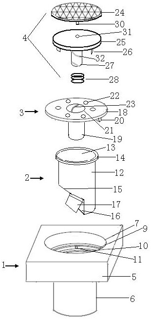
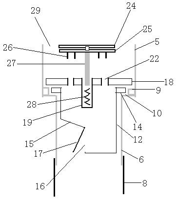
[0016] A floor drain, including a housing 1, an anti-odor mechanism 2, a leaking plate mechanism 3, and a shredding mechanism 4;

[0017] The housing 1 includes a cuboid 5 at the top and a round tube 6 at the bottom. The center of the cuboid 5 is provided with a round hole 7 . Through, the lower end of the round pipe 6 extends into the inlet of the drain pipe 8, and the round hole 7 on the cuboid 5 is sequentially provided with a first annular step 9, a second annular step 10, a first annular step 9, and a second annular step. The opening aperture formed by 10 decreases successively, the height from the first annular step 9 to the upper end surface of the cuboid 5 is greater than the height from the second annular step 10 to the first annular step 9, and the first annular step 9 is used to carry the leakage plate mechanism 3, The second annular step 10 is used to carr...


PUM


Abstract

The invention discloses a floor drain comprising a shell, a deodorization mechanism, a water leaking plate mechanism and a chopping mechanism, and the deodorization mechanism, the water leaking platemechanism and the chopping mechanism are arranged on the shell. The deodorization mechanism can effectively prevent odor and mosquito return overflow in a drain pipe. Only a tread disc of the choppingmechanism needs to be stepped on with a foot, the chopping mechanism can slidably cut obstructions on a water leaking plate, and the chopped obstructions are washed to the drain pipe very easily by running water.

Description

technical field [0001] The invention belongs to the technical field of building drainage, in particular to a floor drain. Background technique [0002] The floor drain is an important interface connecting the building drainage system with the indoor ground. The quality of the floor drain directly affects the indoor air quality, because the drainage pipes and septic tanks of the floor drain are connected with the living space. The old-fashioned floor drain relies on water to form a water seal. Separate the room space from the pipeline system. If there is no water in the floor drain, the drainage pipeline will not be separated from the indoor space. The odor and toxic and harmful gases in the drainage pipeline will overflow along the pipeline and spread in the living room. In addition, after the old-fashioned floor drain is used for a long time, it is easy to accumulate blockages in the floor drain, resulting in poor drainage. Contents of the invention [0003] In order to ...

Claims


Application Information

Patent Timeline
Patent Type & Authority Applications(China)
IPC IPC(8): E03F5/04E03F5/14E03F7/02B02C18/10
CPCB02C18/0092B02C18/10B02C2201/063E03F5/0407E03F5/14E03F7/02E03F2005/0416
Inventor 魏磊
Owner 巩春艳
Why Eureka
Try Eureka