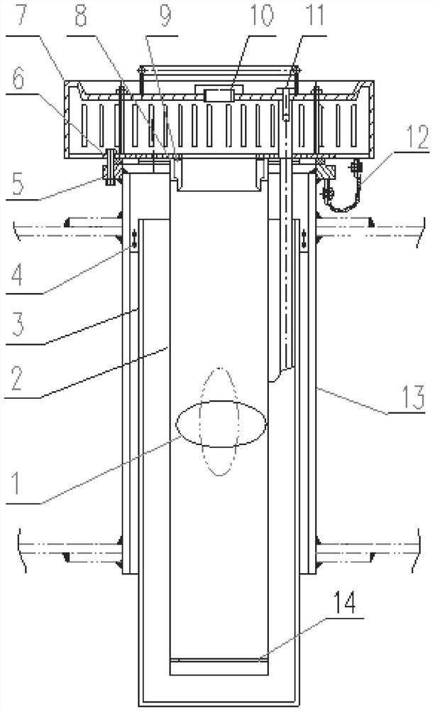
Streamline-shaped float type emergency drainage device

A float-shaped drainage device technology, which is applied in the field of streamlined float-type emergency drainage devices, can solve problems affecting normal use, lack of static conduction devices, safety accidents, etc.

Inactive Publication Date: 2021-05-11
王清
View PDF5 Cites 0 Cited by
  • Summary
  • Abstract
  • Description
  • Claims
  • Application Information

AI Technical Summary

Problems solved by technology

[0003] Publication No. CN2844063 discloses a disc-shaped float emergency drainage device, which includes a diversion cylinder 3, a disc-shaped float 4, an automatic water replenisher 8, a water collection filter 9, etc., and the water seal cylinder 1 is connected to the diversion cylinder 3 through a connecting plate 2. The disc-shaped float 4 is freely placed in the guide tube 3, the guide tube 3 is connected to the valve seat 6 through the connecting bolt 5, the automatic water replenisher 8 is installed on the valve seat 6 through threads, and the water collection filter 9 is installed on the valve seat 6 through the bolt 10. On the valve seat 6; when the installation height of the guide cylinder of this device is low, it is easy to cause the liquid storage to block the water seal cylinder, affecting normal use and increasing the work burden of maintenance personnel; and it does not have a static conductive device, which is prone to static electricity problems cause safety accident

Method used


Image

  • Streamline-shaped float type emergency drainage device

Examples


Embodiment Construction

[0013] The following will clearly and completely describe the technical solutions in the embodiments of the present invention with reference to the accompanying drawings in the embodiments of the present invention. Obviously, the described embodiments are only some, not all, embodiments of the present invention. Based on the embodiments of the present invention, all other embodiments obtained by persons of ordinary skill in the art without making creative efforts belong to the protection scope of the present invention.

[0014] It should be noted that, in the description of the present invention, terms such as "middle", "upper", "lower", "horizontal", "inner" and other indicated directions or positional relationships are based on the directions or positional relationships shown in the drawings. The positional relationship, which is just for convenience of description, does not indicate or imply that the device or element must have a specific orientation, be constructed and oper...


PUM


Abstract

The invention provides a streamline-shaped float type emergency drainage device, belongs to the technical field of emergency drainage devices, and aims to solve the problems that an existing emergency drainage device is large in emergency drainage resistance, a water seal barrel is easily blocked by stored liquid, and the using effect is poor. The drainage device comprises a floater, a flow guide pipe, a water seal cylinder, a connecting support lug, a central disc, a water collection filter cover, a sealing ring valve seat, a sealing ring, an inspection hole, an automatic water replenishing device and a limiting plate and further comprises a floating roof mounting pipe; a plurality of connecting plates are arranged in the floating roof mounting pipe, the water seal cylinder is arranged in the floating roof mounting pipe, and the water seal cylinder and the floating roof mounting pipe are fixedly connected through the connecting plates; a flange is fixedly arranged on the floating roof mounting pipe, and the flange is fixed on the central disc through a bolt; and the floater is a streamline-shaped floater. According to the design, the drainage resistance is smaller, the drainage efficiency is higher, and the performances of water seal evaporation prevention, stored liquid return overflow prevention and condensed oil blockage prevention are better.

Description

technical field [0001] The invention relates to the technical field of emergency drainage devices, in particular to a streamlined float type emergency drainage device. Background technique [0002] Floating roof oil tanks are important equipment in the petrochemical storage and transportation industry. Because of their large size, they are generally set up in the open air. Set in the open air, rainwater will accumulate on the floating roof. Usually the accumulated water is discharged out of the tank through the central drainage pipe of the floating roof. However, when the rainfall exceeds the design displacement of the central drainage pipe, or the drainage pipe is blocked and cannot be drained normally, there will be a large amount of water accumulated on the floating roof. However, when the water accumulated on the floating roof exceeds its floating load capacity, it will cause the floating roof to sink and cause a major safety accident. Therefore, the emergency draina...

Claims


Application Information

Patent Timeline
Patent Type & Authority Applications(China)
IPC IPC(8): B65D88/38B65D90/22B65D90/46
CPCB65D88/38B65D90/22B65D90/46
Inventor 王清卢卫军王福安
Owner 王清
Why Eureka
Try Eureka