
Ultra-small damping rotating device based on the principle of air flotation

A rotating device and damping technology, applied in the direction of electromechanical devices, electrical components, electrical components, etc., can solve the problems of low speed, material strength limitation, high-speed rotation experiments cannot be realized, etc., to eliminate mechanical friction and increase the maximum speed. Effect

Active Publication Date: 2021-07-30
HANGZHOU INNOVATION RES INST OF BEIJING UNIV OF AERONAUTICS & ASTRONAUTICS
View PDF6 Cites 0 Cited by
  • Summary
  • Abstract
  • Description
  • Claims
  • Application Information

AI Technical Summary

Problems solved by technology

Most of the existing rotating devices adopt the structure of bearings, but the bearings also have their own maximum rotational speed, which makes many high-speed rotating experiments impossible.
[0004] Therefore, how to solve the problem that the existing rotating device mostly adopts the structure of the bearing, is limited by the strength of the material, and the problem of low rotational speed is a key technical problem to be solved by those skilled in the art.

Method used


Image

  • Ultra-small damping rotating device based on the principle of air flotation
  • Ultra-small damping rotating device based on the principle of air flotation
  • Ultra-small damping rotating device based on the principle of air flotation

Examples


Embodiment Construction

[0027] The exemplary embodiment will be described in detail herein, and examples thereof are shown in the drawings. The following description is related to the drawings, unless otherwise indicated, the same numbers in the drawings represent the same or similar elements. The embodiments described in the exemplary embodiments are not meant to all embodiments consistent with the present application. Instead, they are only examples of devices or methods consistent with some aspects of the present application.

[0028] In order to make the objects, technical solutions, and advantages of the present invention, the technical solutions of the present invention will be described in detail below. Obviously, the described embodiments are merely the embodiments of the invention, not all of the embodiments. Based on the embodiments of the present invention, all other embodiments obtained without making creative labor without making creative labor, in the premise of creative labor.

[0029] Her...


PUM


Abstract

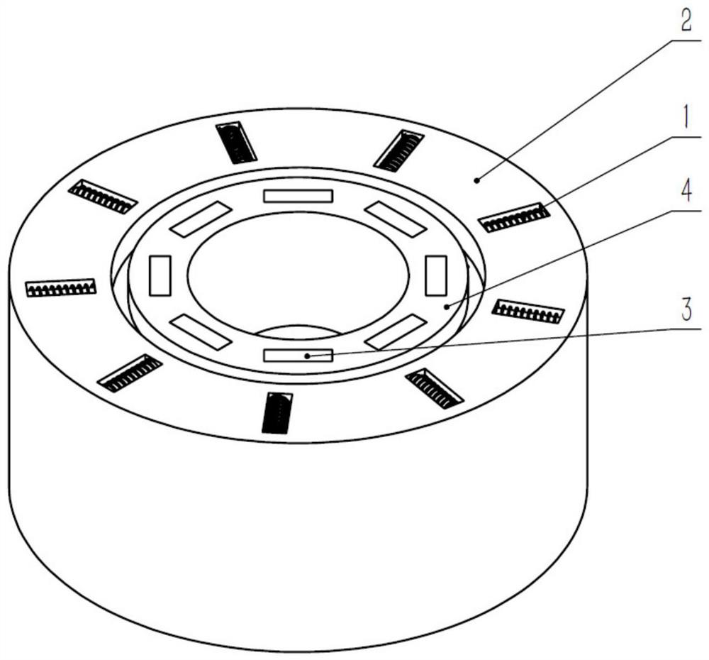
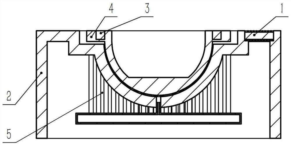
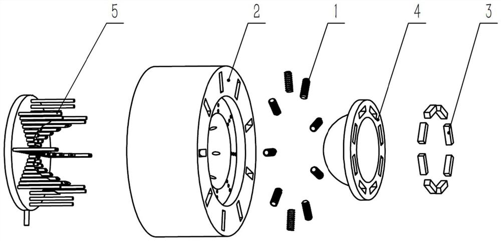
This application relates to the technical field of high rotation, and in particular to an ultra-small damping rotating device based on the principle of air flotation, which includes a stator assembly and a rotor assembly that can rotate relative to the stator assembly. The stator assembly is provided with a groove for the rotor assembly to embed. The cross-sections of the rotor assembly and the groove are set to be circular and gradually decrease from bottom to top. There are evenly distributed in the groove a number of orifices connected with the ventilation pipeline. The rotor assembly is embedded in the groove and Under the action of the air outlet of the orifice, an airflow film is formed between the rotor assembly and the stator assembly. In this way, due to the effect of the airflow film, there will be no mechanical friction between the rotor assembly and the stator assembly. As long as there is a continuous electromagnetic driving force, the rotor assembly can achieve continuous acceleration, and finally achieve the purpose of high-speed rotation, which is conducive to breaking through the speed limit, and realize the high-speed rotation experiment in the laboratory.

Description

Technical field [0001] The present application relates to the field of high-speed rotation, and more particularly to an ultra-small damping rotary device based on air floating principle. Background technique [0002] The motor is the most important component of the motor engineering industry, and even the entire industrial system, and the motion of the motor is based on rotation. In the field of research experiment, it is often necessary to observe the relevant nature of high-speed rotation of research objects. The prior art generally fixes the observation object to the turntable, and the turntable is connected to the motor by mechanical attachment mechanism, and the last motor drive turntable movement. [0003] The advantage of the motor is that the rotation axis is stable and the speed is easy to control. At present, almost all rotating devices are powered by a motor, and then drive turntable through the transmission mechanism. The prior art uses a motor as a power source, and ...

Claims


Application Information

Patent Timeline
Patent Type & Authority Patents(China)
IPC IPC(8): H02K1/27H02K1/12H02K49/10F16C32/06
CPCF16C32/0662F16C2380/26H02K1/12H02K1/276H02K49/106
Inventor 赵正陈伟海裴忠才张益鑫李洋王建华
Owner HANGZHOU INNOVATION RES INST OF BEIJING UNIV OF AERONAUTICS & ASTRONAUTICS
Learn More