Monitoring camera testing management system

A monitoring camera and test management technology, applied in closed-circuit television systems, TV system components, image communication, etc., can solve the problems of automatic shielding, waste of power, etc., to eliminate doubts and discomfort, and enhance privacy protection functions , the effect of reducing loss

Inactive Publication Date: 2020-09-18
张家港市永辉网络科技有限公司
View PDF0 Cites 0 Cited by
  • Summary
  • Abstract
  • Description
  • Claims
  • Application Information

AI Technical Summary

Problems solved by technology

However, the existing monitoring cameras can only realize the functions of multi-directional observation and monitoring, but cannot realize the function of automatic shielding when no monitoring is required (for example, after the user returns home or in a private space in the office)
In addition, the cameras of existing monitoring systems are generally turned on, and are still recording when there is no change in the video picture, which will waste too much power

Method used


Image

  • Monitoring camera testing management system

Examples


Embodiment 1

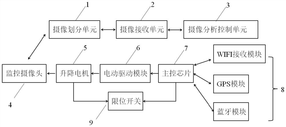
[0037] Embodiment 1 provides a monitoring camera test management system, including a monitoring system and a lifting control system connected to it; the monitoring system includes a camera dividing unit 1, a camera receiving unit 2 and a camera analysis control unit 3; the camera receiving The unit 2 is connected to the camera dividing unit 1 and the camera analysis control unit 3; the lift control system includes a main control chip 5 and a mobile terminal; the main control chip 7 is connected to a signal receiving module 8 and a motor drive module 6; the motor The driving module 6 is connected with a lifting motor 5; the lifting motor 5 is connected with the monitoring camera 4.

[0038] The camera dividing unit 1 is used to divide the camera into a first camera and a second camera; the camera receiving unit 2 is used to obtain video data of the first camera; the camera analysis control unit 3 is used to Video data analysis, if it is obtained that the video data contains a chan...

Embodiment 2

[0043] Embodiment 2 provides a monitoring camera test management system, including a monitoring system and a lifting control system connected to it; the monitoring system includes a camera dividing unit 1, a camera receiving unit 2, and a camera analysis control unit 3; the camera receiving The unit 2 is connected to the camera dividing unit 1 and the camera analysis control unit 3; the lift control system includes a main control chip 5 and a mobile terminal; the main control chip 7 is connected to a signal receiving module 8 and a motor drive module 6; the motor The driving module 6 is connected with a lifting motor 5; the lifting motor 5 is connected with the monitoring camera 4.

[0044] The camera dividing unit 1 is used to divide the camera into a first camera and a second camera; the camera receiving unit 2 is used to obtain video data of the first camera; the camera analysis control unit 3 is used to Video data analysis, if it is obtained that the video data contains a var...

Embodiment 3

[0049] Embodiment 3 provides a monitoring camera test management system, including a monitoring system and a lifting control system connected to it; the monitoring system includes a camera dividing unit 1, a camera receiving unit 2 and a camera analysis control unit 3; the camera receiving The unit 2 is connected to the camera dividing unit 1 and the camera analysis control unit 3; the lift control system includes a main control chip 5 and a mobile terminal; the main control chip 7 is connected to a signal receiving module 8 and a motor drive module 6; the motor The driving module 6 is connected with a lifting motor 5; the lifting motor 5 is connected with the monitoring camera 4.

[0050] The camera dividing unit 1 is used to divide the camera into a first camera and a second camera; the camera receiving unit 2 is used to obtain video data of the first camera; the camera analysis control unit 3 is used to Video data analysis, if it is obtained that the video data contains a vari...


PUM


Abstract

The invention relates to the field of electronic product testing, in particular to a monitoring camera testing management system which comprises a monitoring system and a lifting control system connected with the monitoring system. The monitoring system comprises a camera shooting division unit, a camera shooting receiving unit and a camera shooting analysis control unit. The camera shooting receiving unit is connected to the camera shooting division unit and the camera shooting analysis control unit; the lifting control system comprises a main control chip and a mobile terminal; the main control chip is connected with a signal receiving module and a motor driving module; the motor driving module is connected with a lifting motor; and the lifting motor is connected with the monitoring camera.

Description

Technical field [0001] The invention relates to the field of electronic product testing, in particular to a monitoring camera test management system. Background technique [0002] People pay more and more attention to the security protection of homes or commercial offices. With the development of society and the progress of science and technology, more and more security equipment is widely used in various fields. Household and commercial surveillance cameras are the most widely used. A wide variety. [0003] Currently on the market, surveillance cameras are generally installed on electric pan / tilt. The electric pan / tilt is realized by two executive motors. The motors receive signals from the controller to rotate and position accurately. The surveillance cameras can use the pan / tilt to realize home conditions. Comprehensive monitoring. However, the existing surveillance cameras can only realize the functions of multi-directional observation and monitoring, but cannot realize the f...

Claims


Application Information

Patent Timeline
Patent Type & Authority Applications(China)
IPC IPC(8): H04N17/00H04N5/232H04N7/18
CPCH04N17/002H04N7/181H04N23/66H04N23/651H04N23/695
Inventor 倪向红彭海斌
Owner 张家港市永辉网络科技有限公司
Why Eureka
Try Eureka