Cross beam structure and machine tool having same

A beam and machine tool technology, applied in the field of machine tool equipment, can solve problems such as deformation and insufficient rigidity, achieve the effects of improving stability, avoiding the influence of machining accuracy, and solving deformation

Pending Publication Date: 2020-09-22
ZHUHAI GREE INTELLIGENT EQUIP CO LTD +1
View PDF0 Cites 0 Cited by
  • Summary
  • Abstract
  • Description
  • Claims
  • Application Information

AI Technical Summary

Problems solved by technology

[0004] The main purpose of the present invention is to provide a beam structure and a machine tool with it, so as to solve the technical problem of deformation due to insufficient rigidity of the beam structure in the prior art

Method used


Image

  • Cross beam structure and machine tool having same
  • Cross beam structure and machine tool having same
  • Cross beam structure and machine tool having same

Examples


Embodiment Construction

[0022] It should be noted that, in the case of no conflict, the embodiments in the present application and the features in the embodiments can be combined with each other. The present invention will be described in detail below with reference to the accompanying drawings and examples.

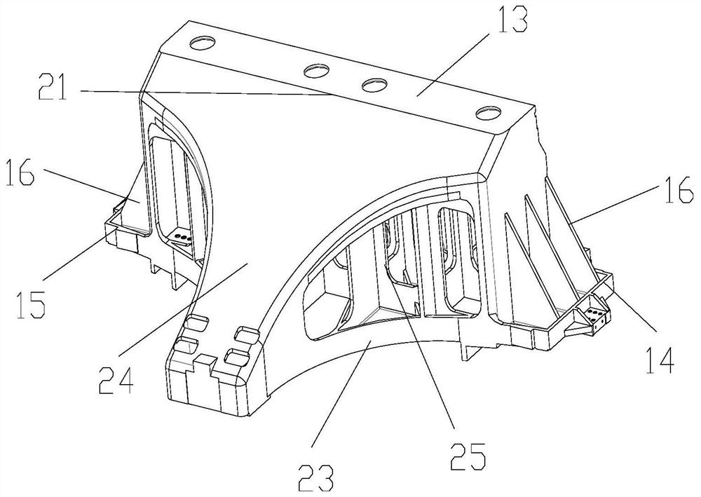
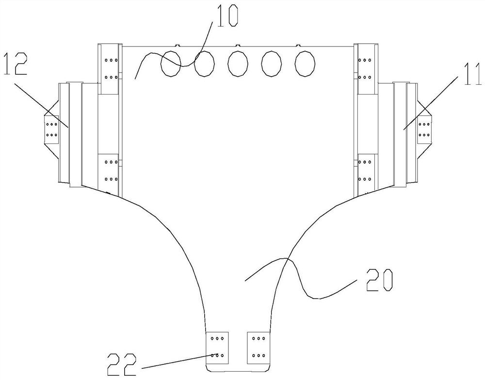
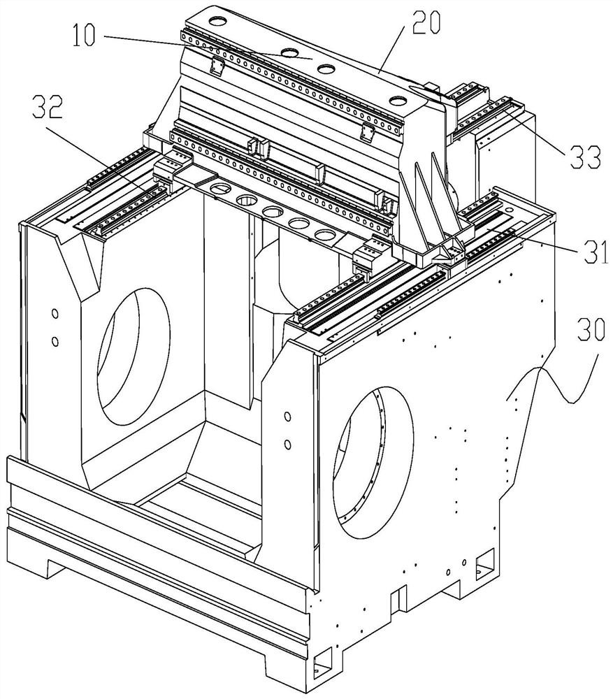
[0023] Such as Figure 1 to Figure 3 As shown, Embodiment 1 of the present invention provides a beam structure, the beam structure includes a first support portion 10 and a second support portion 20, the first support portion 10 extends along a first preset direction, and the first support portion 10 has The first supporting end 11 and the second supporting end 12 are arranged oppositely. The second support part 20 is arranged on the first support part 10, the second support part 20 extends along the second preset direction, the second preset direction and the first preset direction are set at a predetermined angle, and the second support part 20 has an opposite The connection end 21 and the ...


PUM


Abstract

The invention provides a cross beam structure and a machine tool having same. The cross beam structure comprises a first support portion and a second support portion, wherein the first support portionextends in a first preset direction, and is provided with a first support end and a second support end oppositely arranged; the second support portion is disposed on the first support portion, and extends in a second preset direction; the second preset direction and the first preset direction are arranged by a preset angle; the second support portion is provided with a connection end and a thirdsupport end oppositely arranged; the connection end is connected to the first support portion; and the third support end is positioned between the first support end and the second support end to implement supporting by means of the first support end, the second support end and the third support end, so that the technical problem of deformation caused by insufficient rigidity of a cross beam structure in the prior art is solved.

Description

technical field [0001] The invention relates to the technical field of machine tool equipment, in particular to a beam structure and a machine tool having the same. Background technique [0002] At present, the beam is one of the main components of the machine tool, and it mainly plays the role of bearing and supporting in the whole machine equipment. The beam structure of common gantry machine tools is mostly a two-point support structure, that is, supported by both ends of the beam structure. [0003] However, with such a structure, when the headstock moves on the beam for processing tasks, if the stiffness of the beam cannot meet the requirements, the beam structure will be greatly deformed due to the force, which in turn will cause a relatively large impact on the machining accuracy of the machine tool. Impact. Contents of the invention [0004] The main purpose of the present invention is to provide a crossbeam structure and a machine tool with it, so as to solve th...

Claims


Application Information

Patent Timeline
Patent Type & Authority Applications(China)
IPC IPC(8): B23Q1/01
CPCB23Q1/015
Inventor 张博吕鹤黎运尧林蓉
Owner ZHUHAI GREE INTELLIGENT EQUIP CO LTD
Why Eureka
Try Eureka