Turbine and turbine blade tip clearance sealing structure

A technology of blade tip clearance and sealing structure, which is applied in the direction of machines/engines, mechanical equipment, engine components, etc., can solve problems such as difficulty, limited sealing effect, mismatch of speed triangle, etc., to reduce leakage fluid, improve sealing performance, The effect of improving aerodynamic performance

Pending Publication Date: 2020-09-22
HARBIN INST OF TECH
View PDF7 Cites 2 Cited by
  • Summary
  • Abstract
  • Description
  • Claims
  • Application Information

AI Technical Summary

Problems solved by technology

[0004] However, since the tip clearance leakage flow of shrouded turbines does not match the velocity triangle of the main flow, the leakage flow will further affect the aerodynamic parameters of the turbine outlet after it flows out of the outlet cavity. Adding one-sided sealing teeth to the casing or the blade crown has limited sealing effect. How to further improve the sealing performance in the blade crown is not only difficult but also very necessary

Method used


Image

  • Turbine and turbine blade tip clearance sealing structure
  • Turbine and turbine blade tip clearance sealing structure
  • Turbine and turbine blade tip clearance sealing structure

Examples


Embodiment Construction

[0024] Embodiments of the present invention are described in detail below, examples of which are shown in the drawings, wherein the same or similar reference numerals designate the same or similar elements or elements having the same or similar functions throughout. The embodiments described below by referring to the figures are exemplary and are intended to explain the present invention and should not be construed as limiting the present invention.

[0025] The turbine and the blade tip clearance sealing structure of the turbine according to the embodiments of the present invention will be described below with reference to the accompanying drawings.

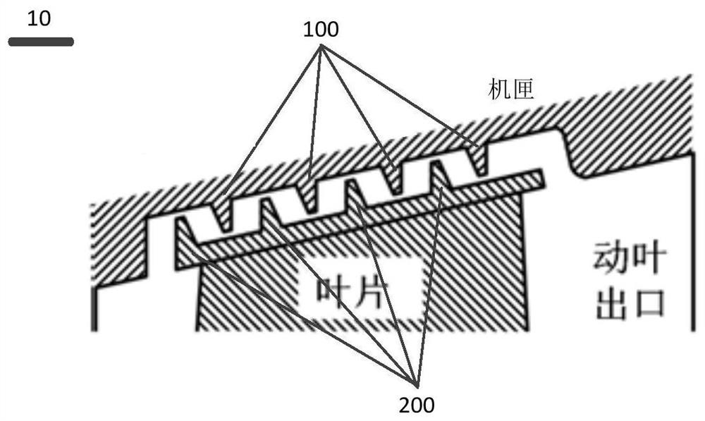
[0026] figure 1 It is a schematic diagram of the sealing structure of the blade tip clearance of the turbine according to the embodiment of the present invention.

[0027] Before introducing the turbine blade tip clearance sealing structure of the embodiment of the present invention, the turbine blade tip clearance sealing stru...


PUM


Abstract

The invention discloses a turbine and a turbine blade tip clearance sealing structure. The turbine comprises a casing and a moving blade, wherein the moving blade comprises a blade tip, and a blade shroud is arranged on the blade tip; the turbine blade tip clearance sealing structure comprises multiple first grate teeth and multiple second grate teeth, the multiple grate teeth are mutually spacedand arranged on the first wall surface, facing the inner wall of the casing, of the blade shroud; and the multiple second grate teeth are mutually spaced and arranged on the inner wall of the casing,and the multiple first grate teeth and the multiple second grate teeth are opposite and arranged in a staggered manner. According to the turbine blade tip clearance sealing structure of the embodiment, the grate teeth are arranged on two sides of the blade shroud to tightly seal the mechanism, leakage of fluid in the blade shroud is reduced maximally, the flowing state of the leaking fluid in theblade shroud is adjusted by proper tooth pitch and tooth thickness, flowing loss of the leaking fluid in the blade shroud and blending loss of the leaking fluid after flowing out of the blade shroud and mainstream fluid are reduced, and therefore, aerodynamic performance of the turbine is improved.

Description

technical field [0001] The invention relates to the technical field of engines, in particular to a turbine and a blade tip clearance sealing structure of the turbine. Background technique [0002] In the flow of the turbine stage, a series of problems caused by tip clearance leakage is one of the important sources of losses in rotating machinery including gas turbines and aeroengines. The problem of clearance leakage has been paid more and more attention, and the flow loss caused by blade tip clearance accounts for more than 1 / 3 of the gas turbine. In order to reduce the leakage flow of the blade tip clearance, relevant technical personnel have proposed many methods, including different methods such as winglets, rib blade tips, casing jets and blade tip jets, all of which can effectively improve the tip leakage flow to a certain extent. The development of the turbine improves the aerodynamic performance of the turbine stage and has been applied in engineering practice. [...

Claims


Application Information

Patent Timeline
IPC IPC(8): F01D11/08
CPCF01D11/08
Inventor 陈绍文李伟航周治华王松涛
Owner HARBIN INST OF TECH
Why Eureka
Try Eureka