A locking cylinder structure with end-of-stroke cushioning

A technology of locking oil cylinder and stroke, applied in the direction of fluid pressure actuating device, etc., can solve the problems of blade damage, large cylinder locking force, large impact, etc., to avoid damage to the oil inlet pipe, enhance safety performance, and avoid tool damage Effect

Active Publication Date: 2022-03-29
CHANGDE LIANJIA MACHINERY
View PDF0 Cites 0 Cited by
  • Summary
  • Abstract
  • Description
  • Claims
  • Application Information

AI Technical Summary

Problems solved by technology

[0003] The purpose of the present invention is to provide a locking cylinder structure with buffering at the end of the stroke to solve the problem that the current cylinder used in the servo tool holder proposed in the above background technology has a large locking force and a large impact when locking, which may easily cause the blade to break. damage, and the slow oil feeding method will lead to a significant reduction in the locking speed of the oil cylinder, which seriously affects the problem of the tool change speed of the servo tool post

Method used


Image

  • A locking cylinder structure with end-of-stroke cushioning
  • A locking cylinder structure with end-of-stroke cushioning
  • A locking cylinder structure with end-of-stroke cushioning

Examples


Embodiment Construction

[0025] The technical solutions in the embodiments of the present invention are clearly and completely described below in conjunction with the accompanying drawings. Apparently, the described embodiments are only a part of the embodiments of the present invention, not all of them. Based on the embodiments of the present invention, all other embodiments obtained by persons of ordinary skill in the art without making creative efforts belong to the protection scope of the present invention.

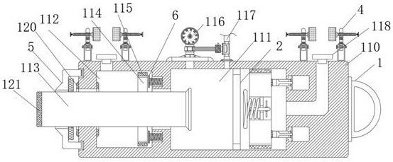
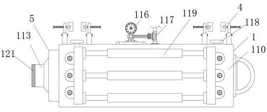
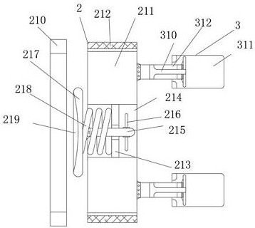
[0026] see Figure 1-8 , an embodiment provided by the present invention: a locking cylinder structure with stroke end buffering, including a hydraulic cylinder body 1, the hydraulic cylinder body 1 includes a working cylinder body 110, and an extrusion chamber is opened inside the working cylinder body 110 111, one side of the working cylinder 110 is provided with a back pressure chamber 112, an extrusion rod 113 is inserted into the back pressure chamber 112, a baffle plate 114 is sleeved o...


PUM


Abstract

The invention discloses a locking oil cylinder structure buffered at the stroke end, which comprises a hydraulic cylinder body. A squeeze chamber is provided inside the working cylinder body of the hydraulic cylinder body. A back pressure chamber is provided on one side of the working cylinder body. The extruding rod is inserted into the chamber, and the inner wall of the extruding chamber is fixedly equipped with a deceleration mechanism. A set of protection mechanisms are installed on both sides of the top of the working cylinder. A cleaning mechanism is provided on the side of the working cylinder outside the extruding rod. A buffer mechanism is provided on the inner wall of the ballast chamber. The present invention uses oil to flow out from the extrusion groove to reduce the speed of the extrusion rod, reduces the impact force of the extrusion rod, and avoids damage to the cutter; uses the cleaning ring knife to clean the waste on the extrusion rod, and uses The sponge snare scrapes the dust on the surface of the extrusion rod to prevent dust from accumulating on the sealing sleeve, making the device less susceptible to dust intrusion.

Description

technical field [0001] The invention relates to the technical field of oil cylinders, in particular to a locking oil cylinder structure with stroke end buffering. Background technique [0002] Hydraulic control is a control method that uses pressured liquid as a control signal transmission. The control system composed of hydraulic technology is called hydraulic control system. Modern processing and production are gradually approaching full mechanization, so hydraulic technology is inseparable. For example, the existing servo tool post generally chooses the oil cylinder to lock, but the oil cylinder used by the servo tool post currently has a large locking force, and the impact when locking is also large, which is easy to cause damage to the blade. The oil method will lead to a significant reduction in the locking speed of the cylinder, which seriously affects the tool change speed of the servo tool post. Therefore, it is necessary to design a locking cylinder structure with ...

Claims


Application Information

Patent Timeline
Patent Type & Authority Patents(China)
IPC IPC(8): F15B15/22F15B15/20F15B15/14
CPCF15B15/22F15B15/20F15B15/1423
Inventor 王建忠王军朱诗广
Owner CHANGDE LIANJIA MACHINERY
Why Eureka
Try Eureka