
Classroom interactive teaching demonstration device

A technology of interactive teaching and demonstration devices, applied in the direction of identification devices, educational tools, electric-operated teaching aids, etc., can solve the problems of inability to carry out teaching demonstrations, inconvenient personalized help for students, and inability to increase the size of the display screen

Inactive Publication Date: 2020-09-22
LIMING VOCATIONAL UNIV
View PDF5 Cites 1 Cited by
  • Summary
  • Abstract
  • Description
  • Claims
  • Application Information

AI Technical Summary

Problems solved by technology

[0002] It takes a long time for teachers to understand each student through contact and teaching activities. They cannot grasp the learning status of each student in real time, and it is inconvenient to provide students with personalized learning help. and exercises, videos or animations, and teaching display devices to show students the teaching content and help students understand the teaching content. There are various types of existing teaching demonstration devices, and the height of the display teaching demonstration device is fixed when it is in use. , the height of the demonstration device cannot be adjusted, and it is difficult for students on both sides and the back row of the classroom to see the demonstration content clearly, and it is inconvenient to rotate the display screen. The size of the display screen is fixed, and the size of the display screen cannot be increased. When the screen teaching demonstration device is placed in the classroom, the students are easy to damage the display screen when they are playing around, and the teaching demonstration cannot be carried out

Method used


Image

  • Classroom interactive teaching demonstration device
  • Classroom interactive teaching demonstration device
  • Classroom interactive teaching demonstration device

Examples


Embodiment approach

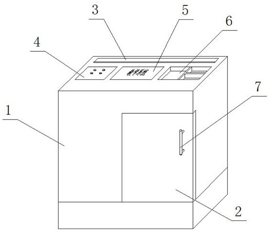
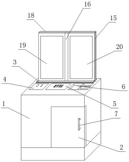
[0021] As a preferred embodiment of the present invention, a box door 2 is provided on one side of the device body 1, a handle 7 is fixedly installed on the box door 2, and a host is installed on the inner side of the box door 2, and the host can The video captured by the camera is stored to facilitate the teacher to understand the learning situation of the students, and the teaching content can be displayed on the first display 18 , the second display 19 and the third display 20 .

[0022] As a preferred embodiment of the present invention, a camera is symmetrically installed on the top of one side of the first display screen 18, and the situation in the classroom can be recorded by the camera, so that the teacher can easily understand the learning status of the students.

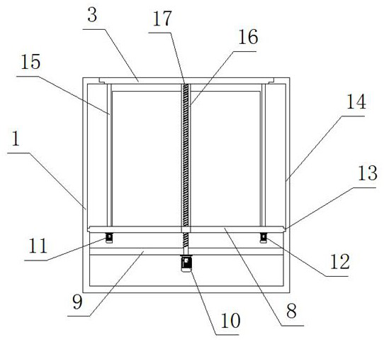
[0023] As a preferred embodiment of the present invention, two sides of the inner wall of the device body 1 are symmetrically provided with sliding grooves 14 , and two ends of the support plate 8 are symme...


PUM


Abstract

The invention provides a classroom interactive teaching demonstration device. The classroom interactive teaching demonstration device comprises a device body, a baffle is fixedly installed at the bottom of the device body, a driving motor is fixedly installed at the bottom of the baffle, a lead screw is fixedly installed on an output shaft of the driving motor, a supporting plate is movably installed at the top of the baffle, and the supporting plate is movably installed on the lead screw through a lead screw nut. According to the classroom interactive teaching demonstration device, the lead screw is driven by the driving motor to lift and store a first display screen, a second display screen and a third display screen, so that the phenomenon that the display screens are damaged due to accidents can be avoided; a left stepping motor and a right stepping motor can drive rotating shafts to adjust the angle between the first display screen and the second display screen and the angle between the first display screen and the third display screen, and the first display screen, the second display screen and the third display screen can display different teaching contents, so that the teaching quality can be improved; and a teacher can conveniently know the learning condition of students through a camera.

Description

technical field [0001] The invention relates to the technical field of teaching demonstration devices, in particular to a classroom interactive teaching demonstration device. Background technique [0002] It takes a long time for teachers to get to know each student through contact and teaching activities. They cannot grasp the learning status of each student in real time, and it is inconvenient to provide students with personalized help in learning. and exercises, videos or animations, and teaching display devices to show students the teaching content to help students understand the teaching content. There are various types of existing teaching demonstration devices, and the height of the display teaching demonstration device is fixed when it is in use. , the height of the demonstration device cannot be adjusted. It is difficult for students on both sides of the classroom and the back row to see the demonstration content, and it is inconvenient to rotate the display screen....

Claims


Application Information

Patent Timeline
Patent Type & Authority Applications(China)
IPC IPC(8): F16M11/04F16M11/08F16M11/18G09B5/02G09F9/302
CPCF16M11/046F16M11/08F16M11/18G09B5/02G09F9/302
Inventor 王星河
Owner LIMING VOCATIONAL UNIV
Learn More