Anti-electric shock power taking mechanism and electric energy meter

A technology of electric shock prevention and electric energy meter, which is applied in the direction of measuring electric variables, instruments, measuring devices, etc., can solve the problems of electric energy meter damage, low safety distance, and easily damaged equipment, so as to improve the service life, reduce the number of arc discharges, The effect of high operational safety

Active Publication Date: 2020-09-22
GUANGDONG POWER GRID CO LTD +1
View PDF6 Cites 0 Cited by
  • Summary
  • Abstract
  • Description
  • Claims
  • Application Information

AI Technical Summary

Problems solved by technology

[0002] In the prior art, when the power-taking wiring is realized on the electric energy meter, there is generally a relatively low safety distance, and the operator is likely to encounter the arc discharge of the electric energy meter during the process of taking electricity, which has a greater risk of electric shock, and the arc discharge is also easy to damage the electric energy. Irreversible damage to the watch, easy to damage the equipment

Method used


Image

  • Anti-electric shock power taking mechanism and electric energy meter
  • Anti-electric shock power taking mechanism and electric energy meter
  • Anti-electric shock power taking mechanism and electric energy meter

Examples


Embodiment 1

[0057] Refer below Figure 1-Figure 4 A specific embodiment of the present invention is described to prevent electric shock and take electricity.

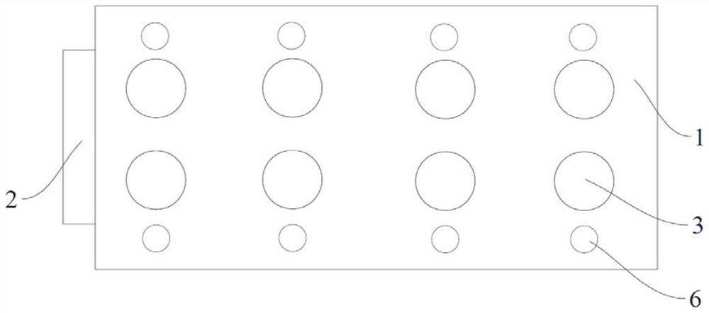
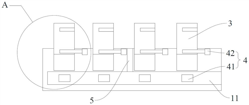
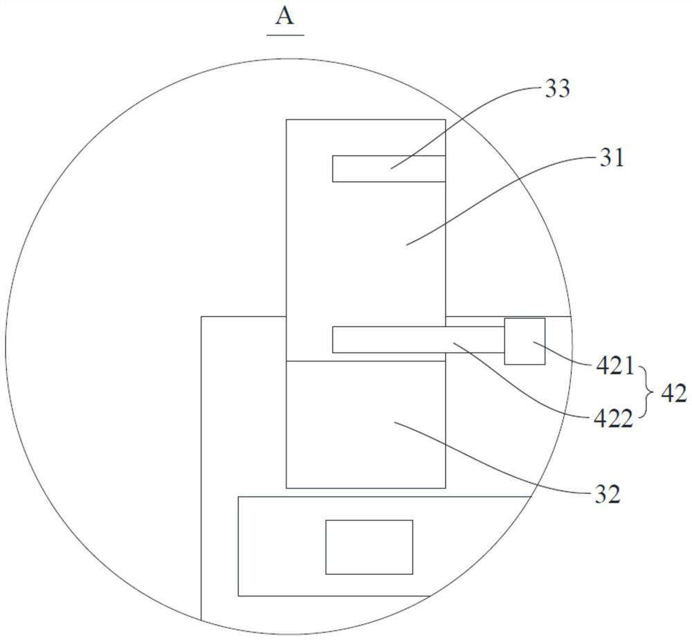
[0058] The anti-shock power-taking mechanism of this embodiment is used to connect the zero wire assembly and / or the live wire assembly in the meter body. The meter body is provided with a live connector, and the live connector is electrically connected to the neutral wire assembly and the live wire assembly inside the meter body. The anti-shock power-taking mechanism includes a housing 1 , a power-taking terminal 3 , a pressing component, a locking component 4 , an insulator 5 and an indicator 6 .

[0059] The casing 1 is provided with a matching groove 11 , and a closing part 2 is slidably arranged in the matching groove 11 , and the closing part 2 is used to close or open the matching groove 11 .

[0060] The power-taking terminal 3 is arranged on the housing 1, and there are multiple power-taking terminals 3. The power-taking ...

Embodiment 2

[0066] The structure of the anti-shock power-taking mechanism of this embodiment is substantially the same as that of Embodiment 1. The difference between the two is the connection structure between the power-taking terminal 3 and the housing 1. Only the difference between the two is made here. Description, the structure of this embodiment is the same as that of Embodiment 1 and will not be repeated here.

[0067] In this embodiment, the power-taking terminal 3 is screw-fitted with the casing 1 .


PUM


Abstract

The invention discloses an anti-electric shock power taking mechanism, which is used for being connected with a zero line assembly and/or a live line assembly in an electricity meter body and comprises a shell and a plurality of power taking wiring terminals, wherein the shell is provided with a matching groove, and a closing piece is arranged in the matching groove in a sliding mode and used forclosing or opening the matching groove; the power taking wiring terminals are movably arranged on the shell in a penetrating mode, each power taking wiring terminal is provided with a power taking position and a power failure position, and when the power taking wiring terminal is located at the power failure position, the power taking wiring terminal is located above the closing piece, is disconnected from the zero line assembly or the live line assembly and can be connected with a wire; when the power taking wiring terminal is located at the power taking position, the power taking wiring terminal is arranged in the matching groove in a penetrating mode, and the power taking wiring terminal is electrically connected with the zero line assembly or the live line assembly.

Description

technical field [0001] The invention relates to the technical field of electric energy metering and collection, in particular to an electric shock-proof power-taking mechanism and an electric energy meter. Background technique [0002] In the prior art, when the power-taking wiring is realized on the electric energy meter, there is generally a relatively low safety distance, and the operator is likely to encounter the arc discharge of the electric energy meter during the process of taking electricity, which has a greater risk of electric shock, and the arc discharge is also easy to damage the electric energy. The watch produces irreversible damage, which is easy to damage the equipment. Contents of the invention [0003] The purpose of the present invention is to propose an electric shock-proof power-taking mechanism, which can reduce the safety risk of the operator accidentally touching the meter body and getting an electric shock, reduce the power-taking risk of the oper...

Claims


Application Information

Patent Timeline
Patent Type & Authority Applications(China)
IPC IPC(8): G01R11/02G01R11/04
CPCG01R11/02G01R11/04Y02T10/7072Y02T10/70
Inventor 陈锦迅冯伟顺
Owner GUANGDONG POWER GRID CO LTD
Why Eureka
Try Eureka