Eureka AIR delivers breakthrough ideas for toughest innovation challenges, trusted by R&D personnel around the world.

Carrier interference elimination method and device, electronic equipment and storage medium

A technology of interference elimination and carrier interference, which is applied in the field of communication, can solve the problems of high cost, lower spectrum efficiency, mutual interference, etc., and achieve the effect of ensuring performance and maintaining spectrum efficiency

Active Publication Date: 2020-09-22
GUANGDONG OPPO MOBILE TELECOMM CORP LTD
View PDF10 Cites 2 Cited by
  • Summary
  • Abstract
  • Description
  • Claims
  • Application Information

AI Technical Summary

Problems solved by technology

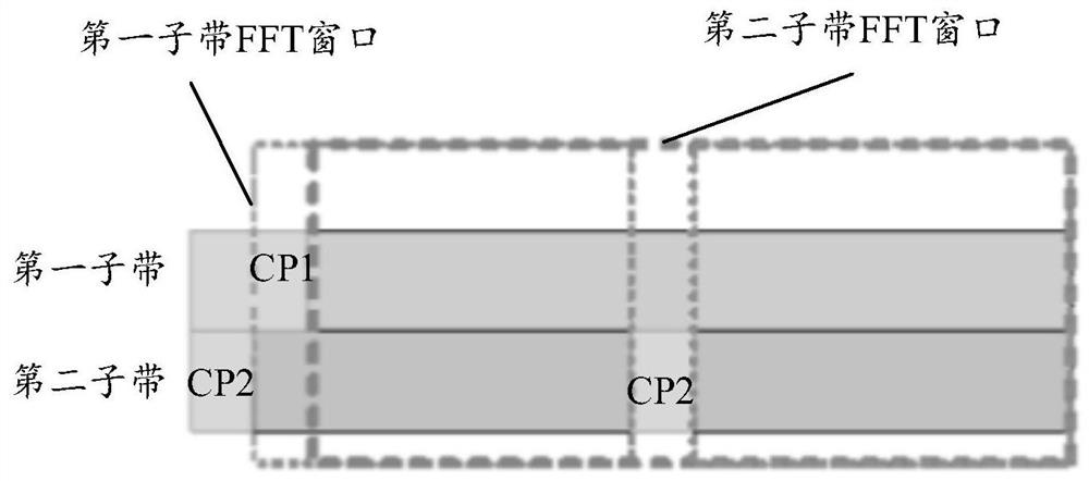
However, in different parameter sets in the frequency domain, due to different subcarrier spacing and cyclic prefix (cyclic prefix, CP) length differences, this will lead to non-orthogonality of subcarriers between subbands using different subcarrier spacing, So that the subcarriers between the subbands using different subcarrier spacings interfere with each other
[0003] A common solution to eliminate mutual interference between sub-carriers in the prior art is to design a bandpass filter for filtering, but this solution usually requires a high-order filter to meet the performance requirements, which has the disadvantages of high complexity and high cost; Alternatively, add empty subcarriers between parameter sets of different SCSs to reduce the impact of inter-numerology interference (INI) between subbands using different subcarrier spacings, but this solution will reduce spectral efficiency , therefore, the problem of how to eliminate the mutual interference between different subcarriers needs to be solved

Method used


Image

  • Carrier interference elimination method and device, electronic equipment and storage medium
  • Carrier interference elimination method and device, electronic equipment and storage medium
  • Carrier interference elimination method and device, electronic equipment and storage medium

Examples


Embodiment Construction

[0027] In order to enable those skilled in the art to better understand the solution of the present invention, the technical solution in the embodiment of the application will be clearly and completely described below in conjunction with the accompanying drawings in the embodiment of the application. Obviously, the described embodiment is only It is a part of embodiments of the present invention, but not all embodiments. Based on the embodiments of the present invention, all other embodiments obtained by persons of ordinary skill in the art without creative efforts fall within the protection scope of the present invention.

[0028] The terms "first", "second" and the like in the description and claims of the present invention and the above drawings are used to distinguish different objects, rather than to describe a specific order. Furthermore, the terms "include" and "have", as well as any variations thereof, are intended to cover a non-exclusive inclusion. For example, a pr...


PUM


Abstract

The embodiment of the invention discloses a carrier interference elimination method and device, electronic equipment and a storage medium. The method comprises the following steps: when a radio frequency transceiver receives a plurality of subcarrier signals of a plurality of sub-bands with different parameter sets in the bandwidth of a bandwidth subset BWP, determining an interference eliminationsubcarrier set i corresponding to the ith sub-band; determining an interference elimination subcarrier set j corresponding to the jth subband, i, j being a positive integer, and constructing a received signal model according to the interference elimination subcarrier set i and the interference elimination subcarrier set j; and performing iterative demodulation and signal interference eliminationon the subcarriers in the interference elimination subcarrier set i and the interference elimination subcarrier set j according to the received signal model, so that interference elimination can be carried out on the received subcarriers in the plurality of subbands of different parameter sets on the premise of maintaining the spectral efficiency, and the performance of received subcarrier signalsis ensured.

Description

technical field [0001] The present application relates to the field of communication technologies, and in particular to a carrier interference elimination method, device, electronic equipment, and storage medium. Background technique [0002] In the 5G New Radio (NR) standard, in order to provide diversified service requirements, the subcarrier spacing (Subcarrier spacing) of the parameter set (numerology) that was simplified in the 4G Long Term Evolution (LTE) standard , SCS) is no longer applicable, 5G NR supports a mixed numerology scheme, and the air interface resources of 5G NR include time domain resources and frequency domain resources, so that it can better provide diversified service requirements. However, for different parameter sets in the frequency domain, due to different subcarrier spacing and cyclic prefix (cyclic prefix, CP) length differences, this will lead to non-orthogonality of subcarriers between subbands using different subcarrier spacing, As a result...

Claims


Application Information

Patent Timeline
Patent Type & Authority Applications(China)
IPC IPC(8): H04L25/03H04B17/391
CPCH04L25/03821H04B17/391
Inventor 刘君
Owner GUANGDONG OPPO MOBILE TELECOMM CORP LTD
Why Eureka
Eureka Blog
Learn More