
An automatic glue dispenser

A technology of dispensing machine and dispensing mechanism, which is applied in the field of dispensing machines, can solve the problems of low work efficiency and achieve the effect of stably pushing workpieces

Active Publication Date: 2021-03-23
深圳市嘉鸿宝科技有限公司
View PDF1 Cites 0 Cited by
  • Summary
  • Abstract
  • Description
  • Claims
  • Application Information

AI Technical Summary

Problems solved by technology

[0004] The above-mentioned technical solution has the following defects: when the glue dispenser processes flat plate-shaped workpieces (such as plates), the workpiece needs to be placed on the stage before the glue dispenser dispenses glue on the workpiece on the stage, and each After processing a workpiece at a time, it is necessary to manually place the workpiece on the carrier, which makes the work efficiency not high

Method used


Image

  • An automatic glue dispenser
  • An automatic glue dispenser
  • An automatic glue dispenser

Examples


Embodiment Construction

[0038] The present invention will be further described in detail below with reference to the accompanying drawings.

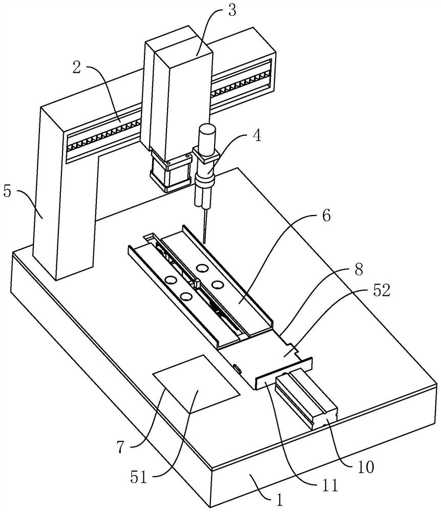
[0039] Refer figure 1 For an automatic dispensing machine according to the disclosure of the present invention, including a table 1, an X-axis motion mechanism 2, a Z-axis moving mechanism 3, and an dispensing mechanism 4, and the edge position of the table 1 is vertically fixed with a bracket 5. The X-axis motion mechanism 2 is fixed to the stent 5, and the Z-axis moving mechanism 3 is slidably coupled to the X-axis moving mechanism 2, and the dispensing mechanism 4 is fixed to the Z-axis moving mechanism 3, and the Z-axis moving mechanism 3 can be along the X-axis. The motion mechanism 2 is slidable, and the dispensing mechanism 4 can be slid along the Z-axis moving mechanism 3; the central position of the table 1 is also provided with a stage 6, and the dispensing mechanism 4 is located directly above the stage 6.

[0040] Refer figure 1 with figure 2 The wor...


PUM


Abstract

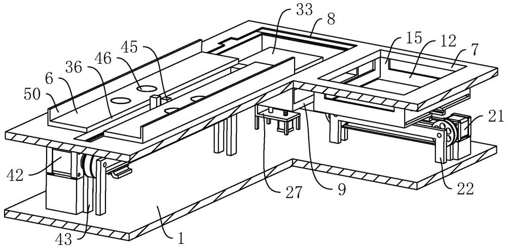
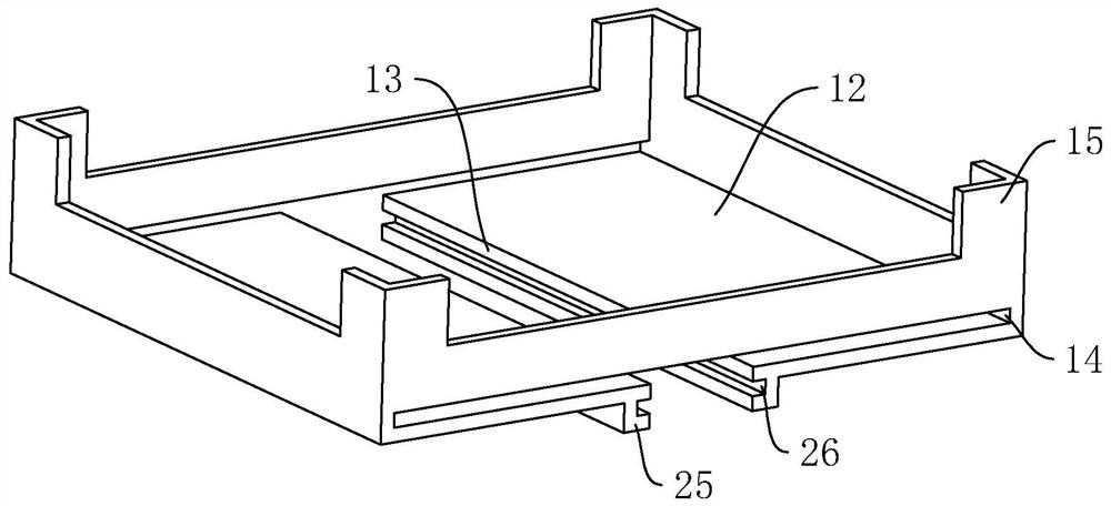
The invention relates to an automatic glue dispenser. The automatic glue dispenser includes a worktable, an X-axis motion mechanism, a Z-axis motion mechanism and a glue dispensing mechanism; a carrier platform is arranged on the worktable; a storage component and a storage board are arranged in the worktable; the bottom of the storage component is provided with a transfer component; a jacking component is arranged in the worktable; the top surface of the worktable is equipped with a discharge port; a pushing part is arranged horizontally on the worktable; a conveying component for conveying the workpiece on the carrier platform is arranged in the worktable; the storage component includes a storage box arranged in the worktable, a long material pushing hole opened at the bottom of the storage box, and a long discharge hole opened at the bottom of the side wall of the storage box; the cross section of the long discharge hole is the same as the cross section of the workpiece; the transfer component is located under the long discharge hole; and the transfer component pushes the workpiece at the bottom of the storage box. The automatic glue dispenser can place a plurality of workpiecesin the storage box at one time; and the conveying component, the jacking component and the pushing part can continuously convey the workpieces to the carrier platform without frequent addition of theworkpieces.

Description

Technical field [0001] The present invention belongs to the technical field of dispensing machine, in particular, to an automatic dispensing machine. Background technique [0002] Dispensing machine is a dispensing apparatus for point-in-line, line, and different shapes of different shapes of a step, line, and surface, also known as a desktop dispensing machine or a triaxial mesh. For electronics, automotive, toys, leather goods, LED or medical equipment and other industries. With the continuous improvement of the manufacturing process of the dispensing machine, the industry that can be applied is constantly expanding. The introduction of automated dot rubber equipment has changed to a large extent, which not only improves the production efficiency of the company, but also guarantees the quality of the product. [0003] The existing bulletin is disclosed in China. China Patent Publication CN207238371U discloses an automatic dispensing machine, including a workbench, an X-axis mot...

Claims


Application Information

Patent Timeline
Patent Type & Authority Patents(China)
IPC IPC(8): B05C5/02B05C13/00
CPCB05C5/0208B05C13/00
Inventor 段伟波徐昌虎易晓氲
Owner 深圳市嘉鸿宝科技有限公司
Learn More