A medical mask cutting device
A mask and material frame technology, which is applied in the field of medical mask blanking device, can solve the problems of cumbersome operation process and large human resources, and achieve the effect of simple operation and labor saving
- Summary
- Abstract
- Description
- Claims
- Application Information
AI Technical Summary
Problems solved by technology
Method used
Image
Examples
Embodiment 1
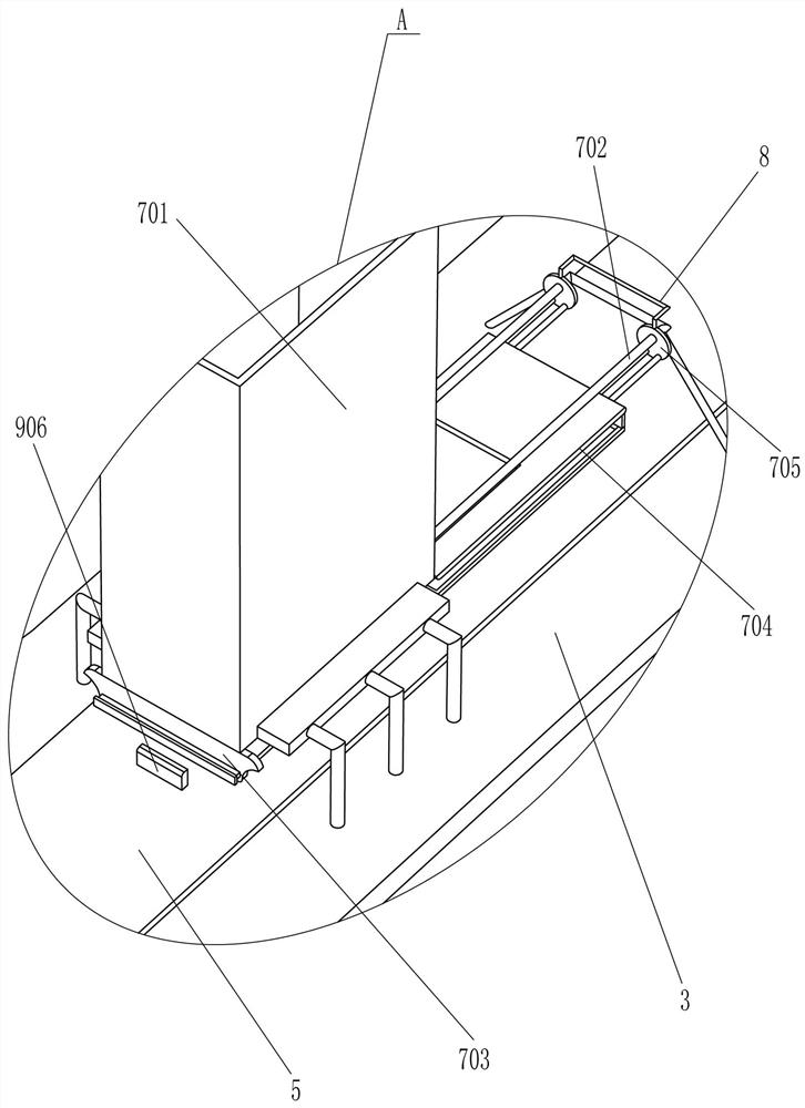
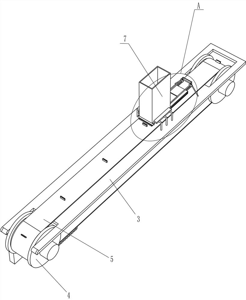
[0026] A medical mask blanking device, such as Figure 1-5 As shown, it includes a first leg 1, a first side plate 2, a first mounting plate 3, a first pulley 4, a first flat belt 5 and a motor 6, and the left and right sides of the top of the first leg 1 are connected with the first One side plate 2, the first mounting plate 3 is connected between the tops of the two first side plates 2, the front and rear parts of the two first side plates 2 are rotatably connected with the first pulley 4, the first pulley 4 The upper part passes through the first mounting plate 3, the first flat belt 5 is wound between the two first pulleys 4, the motor 6 is installed on the front side of the first left side plate 2, the output shaft of the motor 6 is connected to the first The belt pulley 4 is connected, and also includes a blanking device 7, and the first mounting plate 3 is provided with a blanking device 7.
[0027] The blanking device 7 includes a blanking frame 701, a guide rod 702, ...
Embodiment 2
[0030] On the basis of Example 1, such as image 3 As shown, a push rod 8 is also included, and the push rod 8 is connected between the two connecting slide plates 705 .
[0031] When the connecting slide plate 705 needs to be pulled to move, the push rod 8 can be pulled to drive the connecting slide plate 705 to move, which is more convenient to operate.
[0032] Such as Figure 3-5 As shown, transmission device 9 is also included, and transmission device 9 includes L-shaped guide plate 901, slide bar 902, first oblique block 903, first spring 904, second spring 905 and second oblique block 906, blanking The side of the plate 704 away from the baffle plate 703 is connected with an L-shaped guide plate 901, the L-shaped guide plate 901 is slidably connected with a slide bar 902, the bottom of the slide bar 902 is connected with a first oblique block 903, the slide bar 902 and the L-shaped guide plate 901 A first spring 904 is connected between them, and the first spring 904 ...
Embodiment 3
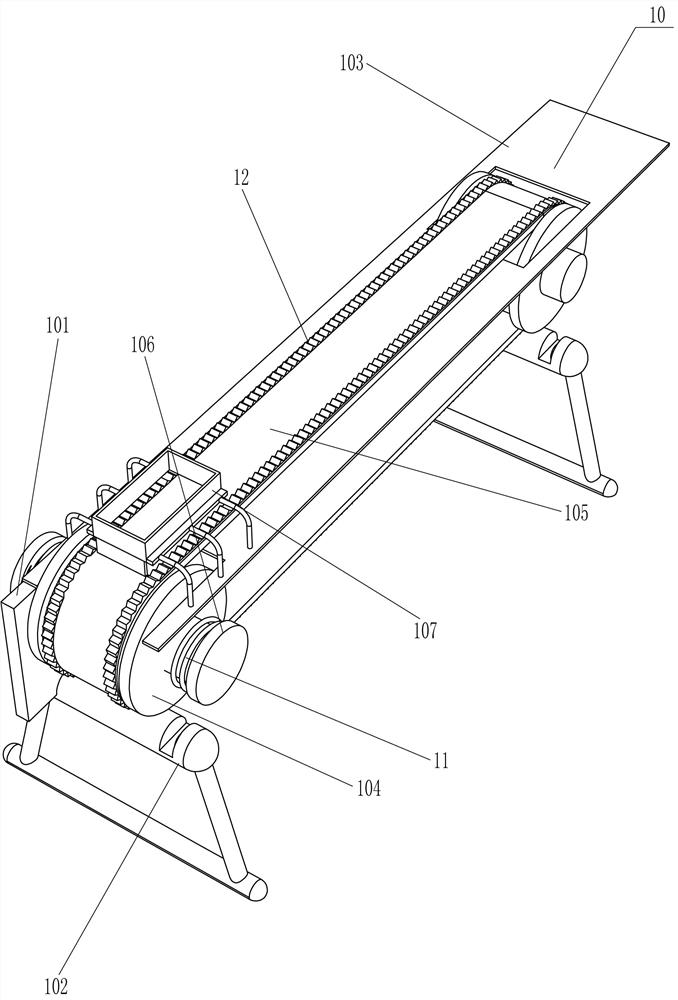
[0035] On the basis of Example 2, such as Figure 6 and Figure 8 As shown, it also includes a pre-release device 10, and the pre-release device 10 includes a second side plate 101, a second leg 102, a second mounting plate 103, a second pulley 104, a second flat belt 105, a turntable 106, a limiter The position frame 107 and the guide plate 108, the second side plate 101 is connected to the rear end of the first side plate 2, the second leg 102 is connected between the bottom of the two second side plates 101, and the top of the two second side plates 101 A second mounting plate 103 is connected between them, and a second pulley 104 is rotatably connected to the front and rear parts between the two sides of the second side plates 101, and the upper part of the second pulley 104 passes through the second mounting plate 103. A second flat belt 105 is wound between the two second pulleys 104, a turntable 106 is connected to the transmission shaft of the second pulley 104 on the...
PUM
 Abstract
Description
Claims
Application Information
 - R&D
- Intellectual Property
- Life Sciences
- Materials
- Tech Scout
- Unparalleled Data Quality
- Higher Quality Content
- 60% Fewer Hallucinations
Browse by: Latest US Patents, China's latest patents, Technical Efficacy Thesaurus, Application Domain, Technology Topic, Popular Technical Reports.
© 2025 PatSnap. All rights reserved.Legal|Privacy policy|Modern Slavery Act Transparency Statement|Sitemap|About US| Contact US: help@patsnap.com


