A device and method for on-machine precision adjustment of turning tool tip height

A precision adjustment and height technology, applied in the direction of feeding devices, automatic control devices, metal processing machinery parts, etc., can solve the problems of low adjustment accuracy, low adjustment accuracy, and inability to remove materials, so as to achieve convenient and fast use and improve calibration Efficiency, convenient and quick adjustment

Active Publication Date: 2022-05-20
DALIAN UNIV OF TECH
View PDF9 Cites 0 Cited by
  • Summary
  • Abstract
  • Description
  • Claims
  • Application Information

AI Technical Summary

Problems solved by technology

[0002] Tool nose center height adjustment is a key technology in turning processing, which has an important impact on ensuring the dimensional accuracy, contour accuracy and wall thickness error of parts. Inconsistency will leave part of the material in the center that cannot be removed, and a small boss will be formed in the center of the part, causing the part to fail to meet the processing requirements. In the processing of the surface of revolution, especially the thin-walled surface of revolution, when both the inner and outer surfaces need to be processed , the part flipping process requires secondary clamping. If the height of the tool tip is inconsistent, in addition to forming a small boss at the center, the contour accuracy and wall thickness error of the rotary parts will be caused because the theoretical track profile of the tool deviates from the actual center of rotation. are difficult to meet the requirements
[0003] At present, in turning processing, there are mainly methods such as trial cutting method and tool microscope observation method for adjusting the height of turning tool tip in turning processing. At the same time, observe the size of the remaining boss, judge and adjust the height of the tool tip. This method is simple and practical, and is widely used in the manufacturing industry. However, the adjustment accuracy of the tool tip height is low, usually from a few microns to tens of microns. The tool setting requirements for accuracy usually use repeated trial cutting, then take the sample under a high-magnification magnifying glass to observe the size of the boss at the center of rotation, and perform repeated trial cutting-measurement-adjustment-trial cutting on the tip of the knife according to the size of the boss , the adjustment process is very complicated. For the processing of special parts, it is necessary to adjust the height of the tool tip after the parts are disassembled. Great inconvenience caused by the process
The tool microscope observation method uses an optical tool microscope to observe and adjust the height of the tool tip in situ. The adjustment process is relatively simple, but the adjustment accuracy is not high, usually at the micron level, and whether it is a trial cutting method or a tool microscope observation method, At present, the height of the tool tip is generally adjusted by adding pads or threaded lifting mechanisms to move the tool tip in the height direction, and the adjustment accuracy is low.
[0004] For the special requirements of aerospace, military, medical, precision instruments and precision physical experiments, etc., precision / ultra-precision machining requirements are put forward for parts, and the dimensional accuracy, surface shape accuracy, contour accuracy, wall thickness error, etc. of the parts are required to reach Micron, submicron or even nanoscale processing requirements, the current tool tip height adjustment method is difficult to meet the adjustment needs of precision / ultra-precision machining process, so a new turning tool tip height on-machine precision adjustment device and method is invented to meet the precision / ultra-precision machining process. Adjustment requirements for tool tip height in the field of ultra-precision machining

Method used


Image

  • A device and method for on-machine precision adjustment of turning tool tip height
  • A device and method for on-machine precision adjustment of turning tool tip height
  • A device and method for on-machine precision adjustment of turning tool tip height

Examples


Embodiment Construction

[0036] The present invention will be described in detail below in conjunction with the accompanying drawings.

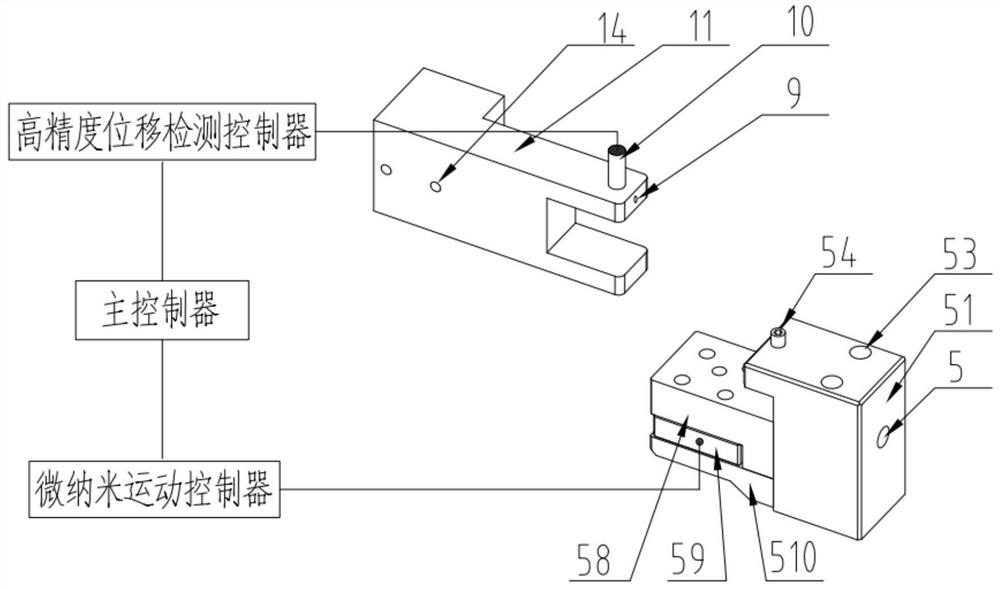
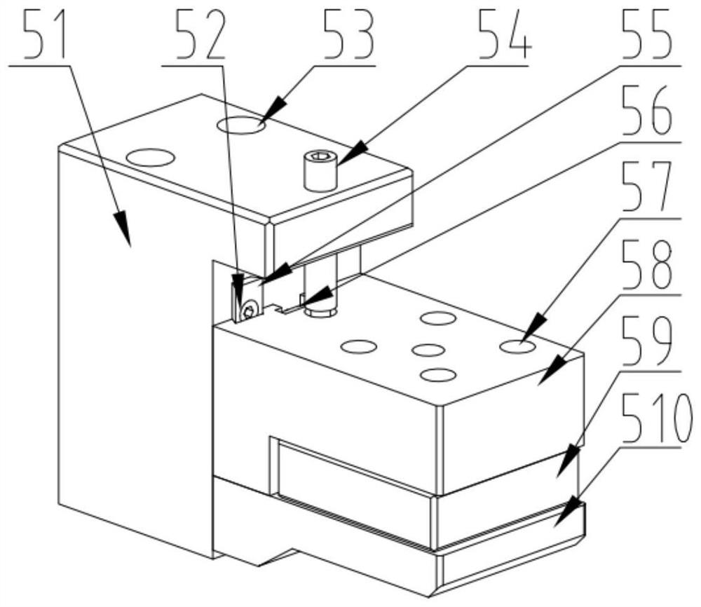
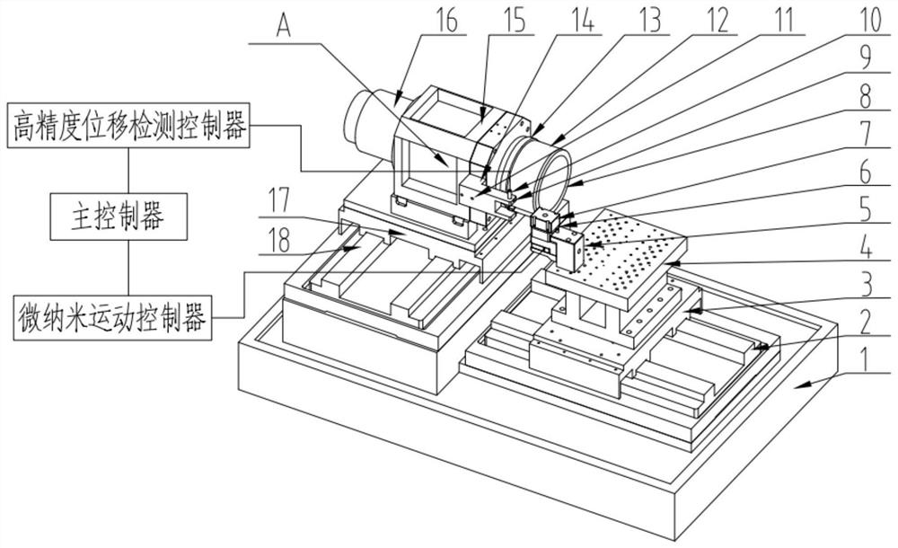
[0037] Such as Figure 1-7 As shown, an on-machine precision adjustment device for turning tool tip height includes a main controller, a tool tip height precision detection device and a tool tip height precision adjustment device;

[0038] The described tool tip height precision detection device includes a high-precision displacement detection controller, a high-precision position detection sensor 10, and a sensor support 11, wherein the high-precision displacement detection controller and the high-precision position detection sensor 10 are connected by a signal line, To form a tool tip height precision detection system, the high-precision position detection sensor 10 is installed on the sensor support 11 and fixed by the sensor locking screw 9, and the sensor support 11 is connected to the spindle seat 15 through the sensor support fixing screw 14. Wherein, the hig...


PUM


Abstract

An on-machine precision adjustment device and method for turning tool tip height, belonging to the field of precision / ultra-precision machining, capable of achieving micron, submicron or even nanometer level precision adjustment, mainly including a main controller, a tool tip height precision detection device and a tool tip height Precision adjustment device. Among them, the tool tip height precision detection device includes high-precision displacement detection controller, high-precision position detection sensor, sensor support, etc.; tool tip height precision adjustment device includes micro-nano motion controller, upper tool holder block locking screw, knife Frame base, dovetail guide rail locking screw, tool holder fixing bolt, differential screw, dovetail guide rail, T-shaped lock nut, upper tool holder block fixing screw, upper tool holder block, micro-nano mobile table, lower tool holder block Wait. The invention has high adjustment precision, realizes the quantitative representation of the knife tip height, can set the required knife tip height according to actual needs, is convenient and quick to adjust, has low dependence on the operator's technology, and is easy to realize automation.

Description

technical field [0001] The invention belongs to the field of precision / ultra-precision machining, and in particular relates to an on-machine precision adjustment device and method for the height of a turning tool tip. Background technique [0002] Tool nose center height adjustment is a key technology in turning processing, which has an important impact on ensuring the dimensional accuracy, contour accuracy and wall thickness error of parts. Inconsistency will leave part of the material in the center that cannot be removed, and a small boss will be formed in the center of the part, causing the part to fail to meet the processing requirements. In the processing of the surface of revolution, especially the thin-walled surface of revolution, when both the inner and outer surfaces need to be processed , the part flipping process requires secondary clamping. If the height of the tool tip is inconsistent, in addition to forming a small boss at the center, the contour accuracy and ...

Claims


Application Information

Patent Timeline
Patent Type & Authority Patents(China)
IPC IPC(8): B23Q15/22B23Q17/22
CPCB23Q15/22B23Q17/2266
Inventor 康仁科焦振华郭江董志刚
Owner DALIAN UNIV OF TECH
Why Eureka
Try Eureka