
Turnover machine for automobile accessory production

A turning machine and auto parts technology, which is applied in the field of auto parts and auto repair, can solve the problems of force deformation at the contact position of the door and the fixture, and affect the appearance of the door, so as to avoid deformation and increase the force bearing area.

Inactive Publication Date: 2020-09-25
广州优讯环保科技有限公司
View PDF0 Cites 2 Cited by
  • Summary
  • Abstract
  • Description
  • Claims
  • Application Information

AI Technical Summary

Problems solved by technology

[0003] Based on the discovery of the above-mentioned inventors, the existing turning machine for auto parts production mainly has the following deficiencies, such as: because the car door is fixed in the fixture, when tightening the screw to fix the parts, the staff needs to move the screwdriver to the car door. The direction of the top will cause the door to be subjected to an upward force, causing the position where the door contacts the fixture to be deformed by force, thus affecting the appearance of the door

Method used


Image

  • Turnover machine for automobile accessory production
  • Turnover machine for automobile accessory production
  • Turnover machine for automobile accessory production

Examples


Embodiment 1

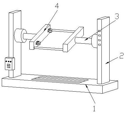
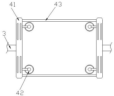
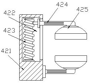
[0026] Example 1: Please refer to Figure 1-Figure 6 , the specific embodiments of the present invention are as follows:

[0027] Its structure includes a base 1, a supporting column 2, an overturning column 3, and a fixture 4. The supporting columns 2 are welded on both sides of the top of the base 1, and there are two overturning columns 3, which are respectively installed on the two supporting columns. 2, both sides of the fixture 4 are welded to the flip column 3, the fixture 4 includes a side plate 41, a clamping device 42, and a connecting rod 43, and the side plate 41 is provided with two, and the clamping There are four devices 42 installed in the two side plates 41 respectively, and two connecting rods 43 are provided and connect the two side plates 41 .

[0028] The clamping device 42 includes a fixed block 421, a groove 422, a threaded block 423, a support rod 424, and a clamping block 425. The inside of the fixed block 421 is provided with a groove 422 in the midd...

Embodiment 2

[0033] Example 2: Please refer to Figure 7-Figure 8 , the specific embodiments of the present invention are as follows:

[0034] The clamping block 425 includes a top cover c1, an elastic rod c2, an engaging block c3, a bottom plate c4, a rotating shaft c5, and a rubber pad c6. The inside of the top cover c1 is hollow, and the elastic rod c2 is embedded in In the middle of the inside of the top cover c1, there are two engaging blocks c3, which are respectively embedded and fixed on both sides of the bottom of the top cover c1, and two bottom plates c4, which are engaged with the engaging blocks c3 , the rotating shaft c5 connects the elastic rod c2 and the two bottom plates c4, the rubber pad c6 is provided with two, and fits on the bottom of the two bottom plates c4, the elastic rod c2 is movably matched with the bottom plate c4, It is beneficial to keep the bottom plate c4 parallel to the door, so as to avoid deformation of the door due to force.

[0035] The rubber pad c...


PUM


Abstract

The invention discloses a turnover machine for automobile accessory production. The turnover machine structurally comprises a base, two supporting columns, two turnover columns and a clamp, the supporting columns are welded to the two sides of the top end of the base, the two turnover columns are installed on the inner sides of the two supporting columns, the two sides of the clamp are connected with the turnover columns in a welded mode, the clamp comprises a side plate, a clamping device and a connecting rod, the clamping device comprises a fixing block, a groove, a threaded block, a supporting rod and a clamping block, the clamping block comprises a top cover, an elastic rod, a clamping block, a bottom plate, a rotating shaft and a rubber pad, and the rubber pad comprises a rubber body,a mounting groove and an anti-skid groove. According to the turnover machine, an elastic rod is in movable fit with two bottom plates through rotating shafts, when thrust is borne by a vehicle door,the bottom plates can be finely adjusted along with the stress direction of the vehicle door, the thrust borne by the vehicle door is shared to the bottoms of the bottom plate, the stress area of thebottom plates to the vehicle door is increased, and deformation of the vehicle door due to through bearing is avoided.

Description

technical field [0001] The invention relates to the field of auto parts and auto repair, in particular to a turning machine for auto parts production. Background technique [0002] Auto parts refer to auto parts, auto parts, car configurations, and car doors are one of the auto parts. When processing car doors, comprehensive operations are required, and when processing other surfaces, it may be due to the angle of the staff. It is convenient to operate, so the turning machine needs to rotate the door to facilitate the operation of the staff. When installing parts on the door, you need to use a screwdriver to fix the parts in the door through screws. When rotating the fixing screws, you need to use force. Push the screwdriver towards the door to fix the parts firmly in the door. [0003] Based on the discovery of the above-mentioned inventors, the existing turning machine for auto parts production mainly has the following deficiencies, such as: because the car door is fixed ...

Claims


Application Information

Patent Timeline
Patent Type & Authority Applications(China)
IPC IPC(8): B25H1/18B25B11/00
CPCB25B11/00B25H1/18
Inventor 陈雪莲
Owner 广州优讯环保科技有限公司
Learn More