AI technical title is built by Patsnap AI team. It summarizes the technical point description of the patent document.
A technology of locking devices and locking parts, which is applied in the direction of transportation and packaging, additional accessories, vehicle parts, etc., can solve the problems of unstable locking, luggage rack detachment, safety accidents, etc., and achieve the effect of convenient operation and stable locking
Active Publication Date: 2020-09-25
DONGFENG MOTOR CO LTD
View PDF10 Cites 2 Cited by
Summary
Abstract
Description
Claims
Application Information
AI Technical Summary
This helps you quickly interpret patents by identifying the three key elements:
Problems solved by technology
Method used
Benefits of technology
Problems solved by technology
[0002] The existing locking structure usually has the problem of unstable locking and easy separation
When the locking structure is used in the luggage rack of a car, it is easy to cause the luggage rack to separate from the vehicle body during bumpy driving, which may easily cause safety accidents
[0003] And some locking structures, the locking is stable, but there is a problem of inconvenient operation, and the user experience is not good
Method used
Image
Click on the blue label to locate the original text in one second.
Reading with bidirectional positioning of images and text.
Examples
Embodiment 1
[0055] Such as Figure 1-4 Shown is a schematic diagram of the push-lock device in Embodiment 1 of the present invention.
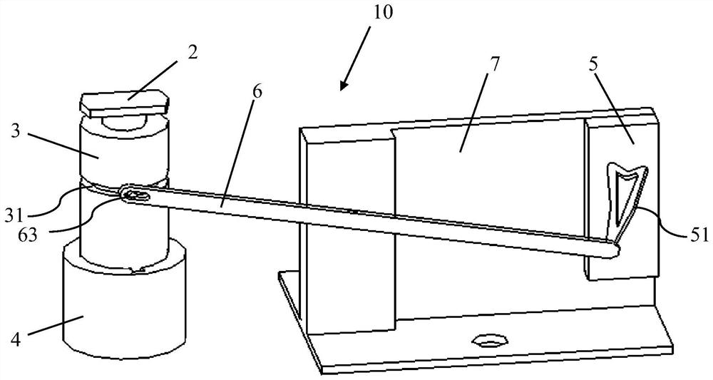
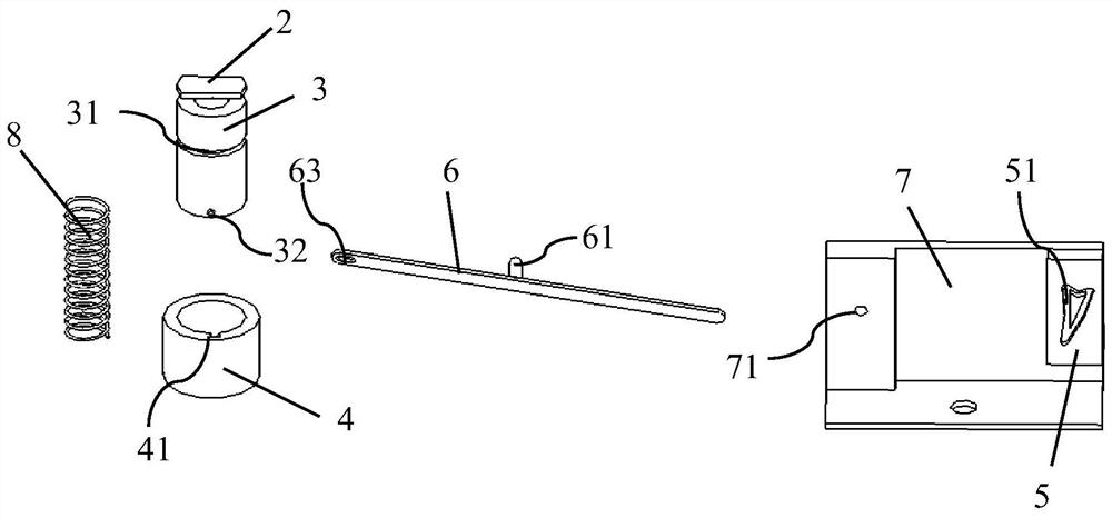
[0056] Such as Figure 1-2 As shown, the push locking device 10 includes a first locking groove 1, a first locking member 2, a pressing member 3, a pressing guide 4, a second locking groove 5 and a second locking member 6;
[0057] One end of the pressing member 3 is connected to the first locking member 2, and the other end is connected to the pressing guide 4, and the pressing guide 4 is used to guide the pressing member 3 to rotate and move up and down;
[0058] One end of the second locking member 6 is connected to the pressing member 3, and the other end is connected to the second locking groove 5;
[0059] The push lock device 10 includes at least a first state and a second state;
[0060] In the first state, the first locking groove 1 locks the first locking member 2;
[0061]When the first locking groove 1 presses the first locking piece 2, th...
Embodiment 2
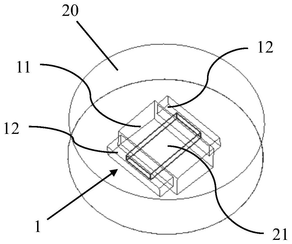
[0119] Such as Figure 9-10 As shown, the luggage rack includes a luggage bar 20, and also includes the push lock device 10 in the first embodiment and its modified example. The first end of the luggage bar 20 is used to be rotatably connected with the roof 30, and the other end is provided with a first Lock slot 1.
[0120] Such as Figure 9 As shown, there are two luggage bars 20, which are respectively located on the left and right sides of the roof 30, arranged roughly along the front and rear directions of the car, and there are also two push locking devices 10.
[0121] Wherein, the push lock device 10a is installed at the rear end of one of the luggage bars 20 , and the press lock device 10b is installed at the front end of the other luggage bar 20 .
[0122] Such as Figure 10 As shown, when the push lock device 10 is unlocked and separated from the luggage bar 20 on the same side, the luggage bar 20 is rotated to lock with the press lock device 10 on the opposite s...
PUM
Abstract
The invention discloses a pressing locking device. The pressing locking device comprises a first locking groove, a first locking piece, a pressing piece, a pressing guide piece, a second locking groove and a second locking piece; one end of the pressing piece is connected with the first locking piece; the other end of the pressing piece is connected with the pressing guide piece; the pressing guide piece is used for guiding the pressing piece to move up and down; one end of the second locking piece is connected with the pressing piece, and the other end of the second locking piece is connectedwith the second locking groove; the pressing locking device at least has a first state and a second state; In the first state, the first locking piece is locked by the first locking groove; when thefirst locking piece is pressed by the first locking groove, the first locking piece and the pressing piece move downwards and rotate forwards, so that the first locking piece and the first locking groove are unlocked, and enter the second state. In the second state, the second locking piece and the second locking groove are locked; when the first locking groove is pressed again, the second lockingpiece and the second locking groove are unlocked, and the first locking piece and the pressing piece move upwards and rotate reversely, and enter the first state.
Description
technical field [0001] The invention relates to the technical field of automobiles, in particular to a push locking device. Background technique [0002] The existing locking structure usually has the problems of unstable locking and easy separation. When the locking structure is used in the luggage rack of a car, it is easy to cause the luggage rack to separate from the vehicle body during bumpy driving, which may easily cause safety accidents. [0003] And some locking structures, the locking is stable, but there is the problem of inconvenient operation, and the user experience is not good. [0004] Therefore, it is necessary to design a push lock device that takes into account both convenient operation and stable locking. Contents of the invention [0005] The purpose of the present invention is to overcome the disadvantages of the prior art and provide a push lock device that takes into account both convenient operation and stable locking. [0006] The technical sol...
Claims
Application Information
Patent Timeline
Application Date:The date an application was filed.
Publication Date:The date a patent or application was officially published.
First Publication Date:The earliest publication date of a patent with the same application number.
Issue Date:Publication date of the patent grant document.
PCT Entry Date:The Entry date of PCT National Phase.
Estimated Expiry Date:The statutory expiry date of a patent right according to the Patent Law, and it is the longest term of protection that the patent right can achieve without the termination of the patent right due to other reasons(Term extension factor has been taken into account ).
Invalid Date:Actual expiry date is based on effective date or publication date of legal transaction data of invalid patent.

