
Vehicle speed control method and device in automatic driving mode, equipment and medium

A vehicle speed control and automatic driving technology, which is applied in the control device, non-electric variable control, speed/acceleration control and other directions, can solve the problems of not being able to reach the vehicle running speed, consuming a lot of time and labor, etc.

Active Publication Date: 2020-09-25
WERIDE CORP
View PDF6 Cites 6 Cited by
  • Summary
  • Abstract
  • Description
  • Claims
  • Application Information

AI Technical Summary

Problems solved by technology

[0004]However, driving conditions, vehicle weight, changes in vehicle interior sensor settings, wheel wear, and varying degrees of pedal calibration all affect how quickly an autonomous vehicle can operate, making Simply relying on the control instructions sent by the vehicle central controller cannot achieve the purpose of accurately and timely controlling the running speed of the vehicle, and due to the slight differences in the internal hardware structure of the same type of vehicle during the production process (for example, pedal mechanical installation error), in order to ensure the uniformity of vehicle speed control, the pedals of each vehicle must be calibrated before the vehicle leaves the factory, which consumes a lot of time and labor.

Method used


Image

  • Vehicle speed control method and device in automatic driving mode, equipment and medium
  • Vehicle speed control method and device in automatic driving mode, equipment and medium
  • Vehicle speed control method and device in automatic driving mode, equipment and medium

Examples


Embodiment 1

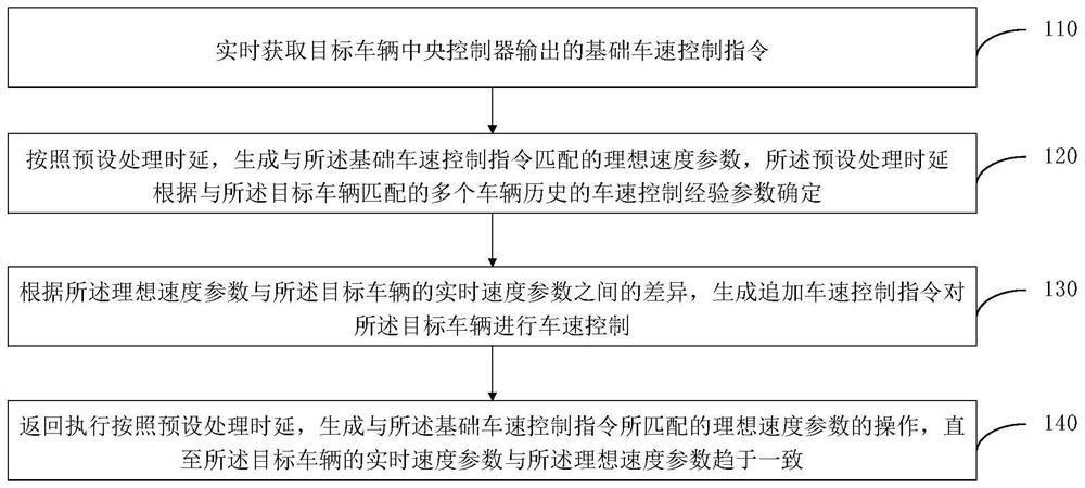
[0032] figure 1 It is a flowchart of a vehicle speed control method in the automatic driving mode provided by Embodiment 1 of the present invention. This embodiment is applicable to the situation of controlling the vehicle speed of a vehicle in the automatic driving mode. The method can be provided by the embodiment of the present invention. The vehicle speed control device in the automatic driving mode can be implemented by means of software and / or hardware, and can be integrated in a general electronic device. Typically, the device is a central controller that can be adapted to an automatic driving vehicle port device.

[0033] In the prior art, when the vehicle is in the automatic driving mode, the speed of the vehicle is controlled based on an inherent vehicle speed control system to ensure that the vehicle runs at a desired speed. The inherent vehicle speed control system generally defines the desired acceleration according to the desired speed set at the desired positio...

Embodiment 2

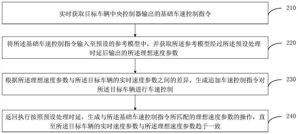
[0051] figure 2 It is a flow chart of a vehicle speed control method in the automatic driving mode provided by Embodiment 2 of the present invention. This embodiment can be combined with various optional solutions in the above-mentioned one or more embodiments. In this embodiment, according to the preset Processing time delay, generating an ideal speed parameter that matches the basic vehicle speed control instruction may be: input the basic vehicle speed control instruction into a preset reference model, and obtain the reference model through the preset processing The ideal speed parameter output after time delay.

[0052] Correspondingly, the method of the embodiment of the present invention includes:

[0053] Step 210, acquiring the basic vehicle speed control command output by the central controller of the target vehicle in real time.

[0054] Specifically, the basic vehicle speed control command is an acceleration control command, and the acceleration command is used t...

Embodiment 3

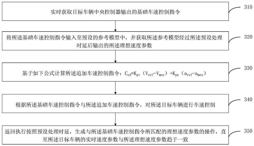
[0072] image 3 It is a flow chart of a vehicle speed control method in the automatic driving mode provided by Embodiment 3 of the present invention. This embodiment can be combined with each optional solution in one or more of the above embodiments. In this embodiment, according to the The difference between the ideal speed parameter and the real-time speed parameter of the target vehicle is used to generate an additional vehicle speed control instruction to perform vehicle speed control on the target vehicle, which may be: calculate the additional vehicle speed control instruction based on the following formula: C ad =K pv (V ref -V mea )+K pa (a ref -a mea ); performing vehicle speed control on the target vehicle according to the basic vehicle speed control instruction and the additional vehicle speed control instruction.

[0073] Correspondingly, the method of the embodiment of the present invention includes:

[0074] Step 310, acquiring the basic vehicle speed cont...


PUM


Abstract

The embodiment of the invention discloses a vehicle speed control method and device in an automatic driving mode, equipment and a medium. The method comprises the steps of acquiring a basic vehicle speed control instruction output by a target vehicle central controller in real time; generating an ideal speed parameter matched with the basic vehicle speed control instruction according to preset processing time delay; according to the difference between the ideal speed parameter and the real-time speed parameter of the target vehicle, generating an additional vehicle speed control instruction tocontrol the vehicle speed of the target vehicle; and returning to execute the operation of generating the ideal speed parameter matched with the basic vehicle speed control instruction according to the preset processing time delay until the real-time speed parameter of the target vehicle tends to be consistent with the ideal speed parameter. According to the technical scheme, the vehicle speed ofan automatic driving vehicle can be accurately and timely controlled, and the production time and the production labor force of the automatic driving vehicle are saved.

Description

technical field [0001] Embodiments of the present invention relate to the technical field of signal control, and in particular to a vehicle speed control method, device, equipment and medium in an automatic driving mode. Background technique [0002] As self-driving vehicles are approaching practicality, how to accurately and effectively control the speed of self-driving vehicles has become a common concern. [0003] In the existing automatic driving technology, the vehicle's pedals (acceleration pedal and brake pedal) are controlled by sending control commands through the inherent vehicle speed control system integrated in the vehicle's central controller, so as to achieve the purpose of adjusting the vehicle's running speed . [0004] However, the driving environment, vehicle body weight, changes in vehicle internal sensor settings, wheel wear, and different calibration levels of the pedals will all affect the operating speed of the self-driving vehicle, making it impossi...

Claims


Application Information

Patent Timeline
Patent Type & Authority Applications(China)
IPC IPC(8): B60W60/00B60K31/00
CPCB60W60/001B60K31/00B60W2720/00B60K31/04B60W30/143B60W50/06B60W2050/0083B60W2720/10B60W2720/106B60W2556/10B60W2050/0075G05D1/0221G05D1/0223
Inventor 熊武
Owner WERIDE CORP
Learn More