
Combined construction structure of underground road and ground bridge

An underground road and ground technology, applied in bridge construction, roads, bridges, etc., can solve the problems of time-consuming and laborious installation, road pulling, heavy weight, etc., and achieve the effects of convenient operation, smooth road surface and simple structure

Inactive Publication Date: 2020-09-25
杭州很美网络科技有限公司
View PDF7 Cites 3 Cited by
  • Summary
  • Abstract
  • Description
  • Claims
  • Application Information

AI Technical Summary

Problems solved by technology

[0004] The purpose of the present invention is to provide a joint construction structure of underground roads and ground bridges, to solve the traditional problem of the above-mentioned background technology for the gap left at the docking position of the bridge and the road surface for the integrated steel structure plate to be fixed and connected. , due to the integrated design, the heavy weight requires the use of large-scale machinery for hoisting and installation during handling and movement, which makes the installation very time-consuming and laborious. At the same time, there is still a gap after the installation to make the vehicle pass by The wear and tear of the tires will have an impact. After the integrated fixed installation, the bridge body will vibrate and shake when it is used later, so that the bridge body will drive the mounting parts and the road surface to act together when shaking and vibrating, making the road surface The problem that caused the pull to appear damaged

Method used


Image

  • Combined construction structure of underground road and ground bridge
  • Combined construction structure of underground road and ground bridge
  • Combined construction structure of underground road and ground bridge

Examples


Embodiment Construction

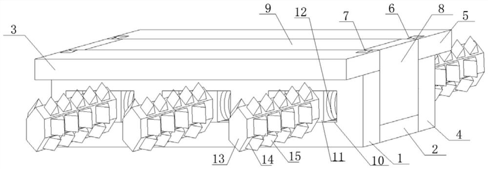
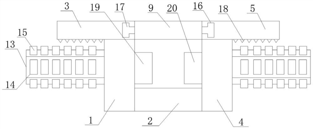
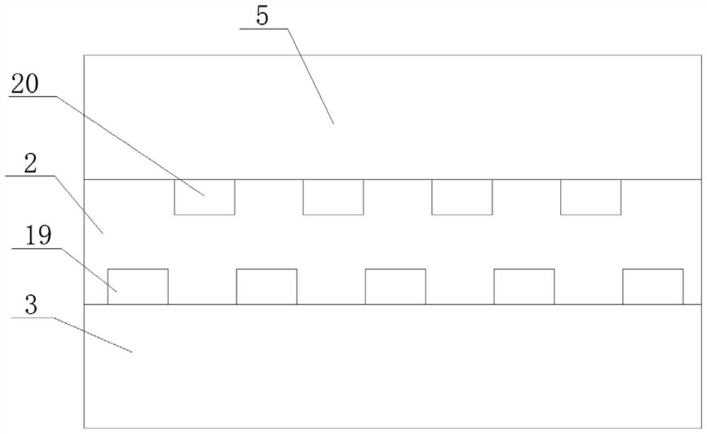
[0027] see Figure 1-3 , in an embodiment of the present invention, a joint construction structure of an underground road and a bridge on the ground, comprising a side riser-1, one side of the side riser-1 is horizontally welded with a fixed base plate 2, and one side of the side riser-1 The side is horizontally welded with a cover connecting plate 3, and the fixed bottom plate 2 is horizontally welded on one side of the side vertical plate 1 near the bottom surface, and the bottom surface of the fixed bottom plate 2 and the bottom surface of the side vertical plate 1 are kept at the same level, and the cover is connected Plate one 3 is horizontally welded on the side of side vertical plate one 1 away from the fixed bottom plate 2 and close to the top surface, and the top surface of cover plate one 3 is kept at the same level as the top surface of side vertical plate one 1, and the fixed bottom plate 2 Side vertical plate two 4 is horizontally welded with side vertical plate t...


PUM


Abstract

The invention discloses a combined construction structure of an underground road and a ground bridge and relates to the field of road and bridge construction. The combined construction structure comprises a first side vertical plate; a fixed bottom plate is horizontally welded to one side edge of the first side vertical plate; a first cover connecting plate is horizontally welded to one side edgeof the first side vertical plate; a second side vertical plate is horizontally welded to the side edge, away from the first side vertical plate, of the fixed bottom plate; a second cover connecting plate is horizontally welded to the side edge, away from the fixed bottom plate, of the second side vertical plate; clamping grooves are symmetrically formed in the top surfaces of the first cover connecting plate and the second cover connecting plate in a vertical direction; stable clamping strips are vertically inserted into the inner side edges of the clamping grooves. The device is designed intoa split structure and is simple in structure and convenient to operate; by means of a splicing mode, installation is simpler during the installation of the combined construction structure, and certain convenience is brought to the carrying and moving of the combined construction structure; multiple clamping and fixing structures, so that connection positions are more stable; connection between abridge body and a road surface is more stable with a certain buffering effect realized.

Description

technical field [0001] The invention relates to the technical field of road and bridge construction, in particular to a joint construction structure of an underground road and a ground bridge. Background technique [0002] Road bridges are generally composed of several parts such as roadbed, road surface, bridge, tunnel engineering and traffic engineering facilities. With the vigorous development of the transportation industry, the number of high-grade highways mainly including expressways and first-class highways has increased year by year, and my country's highway industry has entered a new stage focusing on the construction of high-grade highways. High-grade highways should pay special attention to the design of the linear shape, maintain the continuity of the linear shape, and make passengers feel safe and comfortable physically and psychologically. [0003] Nowadays, there are more and more expressways and urban roads. When building roads, it is necessary to cross a va...

Claims


Application Information

Patent Timeline
Patent Type & Authority Applications(China)
IPC IPC(8): E01C1/00E01D1/00E01D19/00E01C3/00
CPCE01C1/002E01C3/00E01D1/00E01D19/00
Inventor 李娟
Owner 杭州很美网络科技有限公司
Learn More