Water conservancy monitoring device for water conservancy project and using method thereof
A monitoring device and water conservancy engineering technology, applied in the direction of measuring devices, sampling devices, sampling, etc., can solve the problems of inconvenient detection of water quality, inability to realize position adjustment, inability to realize collection of multiple samples, etc., and achieve the effect of reducing offset positions
- Summary
- Abstract
- Description
- Claims
- Application Information
AI Technical Summary
Problems solved by technology
Method used
Image

Examples
Embodiment 1
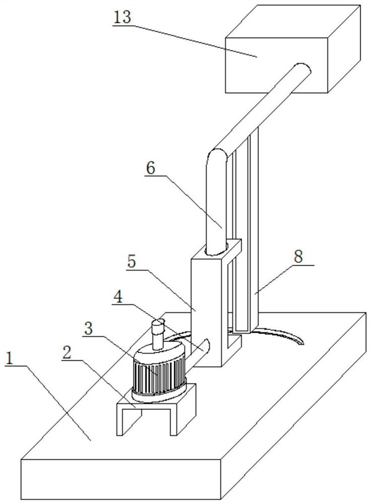
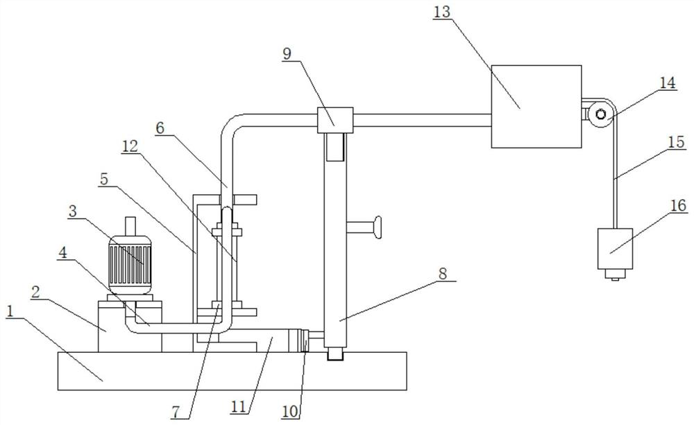
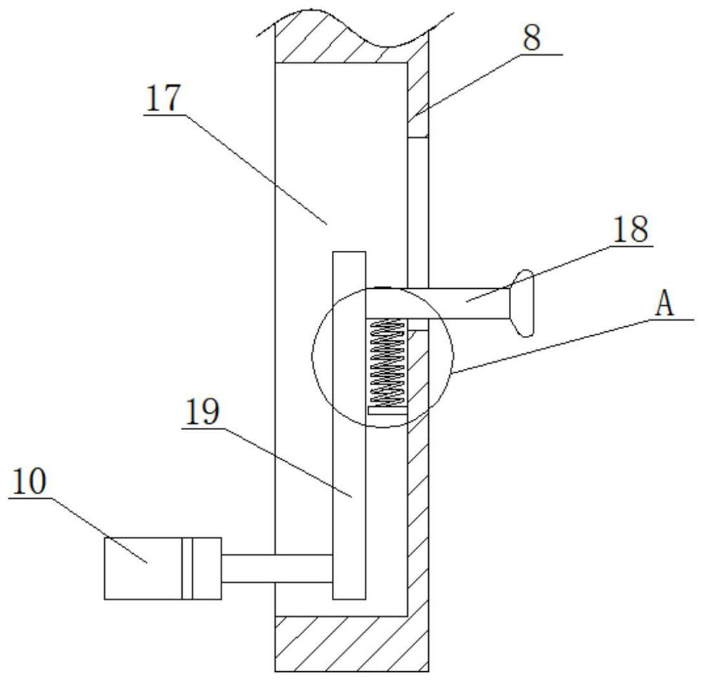
[0047] Example 1: as Figure 1-9 As shown, a water conservancy monitoring device for a water conservancy project includes a base 1, a mounting frame 2 and a fixing frame 5 are fixedly installed on the top of the base 1, and the mounting frame 2 is located on one side of the fixing frame 5, and the top of the mounting frame 2 is fixed The suction pump 3 is installed, and the support plate 40 is fixedly installed in the fixing frame 5. The top of the support plate 40 is sealed and clamped with the sampling tube 12, and the suction end of the suction pump 3 extends into the installation frame 2 and is fixedly installed with a suction tube. 4. One end of the suction tube 4 extends into the fixing frame 5 and extends above the support plate 40. The suction tube 4 is sealed and clamped with the sampling tube 12, the fixing frame 5 is rotatably connected with the support tube 6, and the bottom of the support tube 6 is installed. The end seal is rotatably connected with a water outlet...
Embodiment 2
[0060] Embodiment 2: as Figure 10-15 As shown, a water conservancy monitoring device for a water conservancy project, the difference between this embodiment and the first embodiment is that two mounting plates 21 are fixedly installed on the inner wall of the mounting box 13, and the reeling shaft 22 rotates with the two mounting plates 21 respectively. The inner wall of the winding shaft 22 is fixedly installed with a stabilizer bar 23, and the output shaft of the brake motor 26 extends into the winding shaft 22 and is fixedly connected to one side of the stabilizer bar 23, and is fixedly installed on the inner wall of one side of the winding shaft 22. There is a fixed pipe 27, and one end of the fixed pipe 27 extends into the installation box 13 and is fixedly connected with the other end of the connecting pipe 15, one end of the fixed pipe 27 is sealed and fixedly connected with the other end of the conveying pipe 24, and one end of the conveying pipe 24 is sealed A rotati...
PUM
 Abstract
Description
Claims
Application Information