Numerical control milling machine

A technology of CNC milling machine and milling cutter disc, applied in the field of CNC machine tools, can solve the problems of bolts, milling cutter cracking, excessive rotation of bolts, unfavorable milling cutter processing, etc., to improve the stability, reduce thermal wear, and improve machining accuracy. Effect

Inactive Publication Date: 2020-11-24
曾群英
View PDF0 Cites 0 Cited by
  • Summary
  • Abstract
  • Description
  • Claims
  • Application Information

AI Technical Summary

Problems solved by technology

[0003] The CNC milling machine needs to use the tool in the processing. The tool is installed on the cutter head. The cutter head is an important component of the CNC milling machine. However, the existing milling cutter and the cutter head are installed and fixed by bolts. If the installation and rotation of the bolts is in the same direction as the rotation of the cutter head, the long-term high-speed rotation of the cutter head and the force generated by the milling cutter and the workpiece will cause the bolts to be affected and loosen, which is not conducive to the milling cutter's machining. For the processing of workpieces, if the installation rotation of the bolts is opposite to the rotation direction of the cutter head, the bolts will be over-rotated due to the influence of the rotation force, which will easily lead to the cracking of the bolts and milling cutters

Method used


Image

  • Numerical control milling machine
  • Numerical control milling machine
  • Numerical control milling machine

Examples


Embodiment

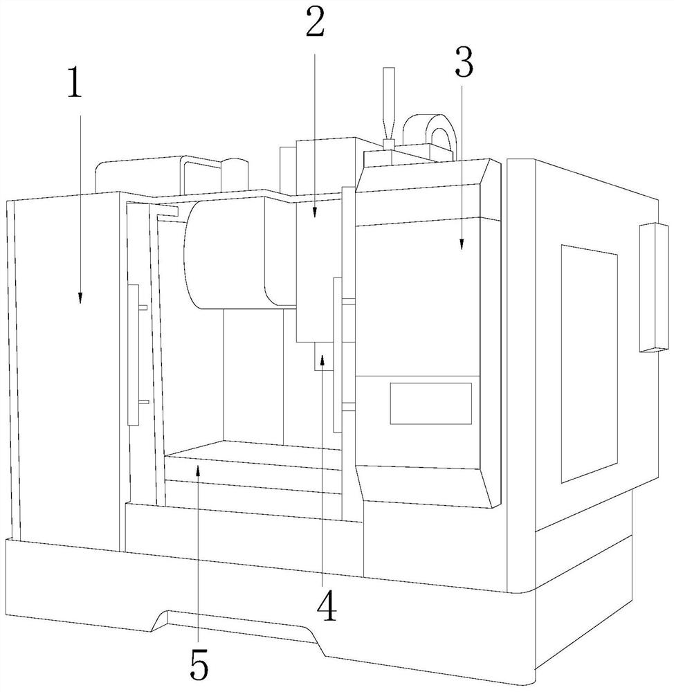
[0033] see Figure 1-10 , the present invention provides a technical scheme of a numerically controlled milling machine: its structure includes a body 1, a spindle box 2, a controller 3, a milling cutter head 4, and a workbench 5, and the body 1 is equipped with a controller 3, and the controller 3 Connected with the spindle box 2, the bottom of the spindle box 2 is equipped with a milling cutter disc 4, and a workbench 5 connected with the machine body 1 is arranged below the milling cutter disc 4.

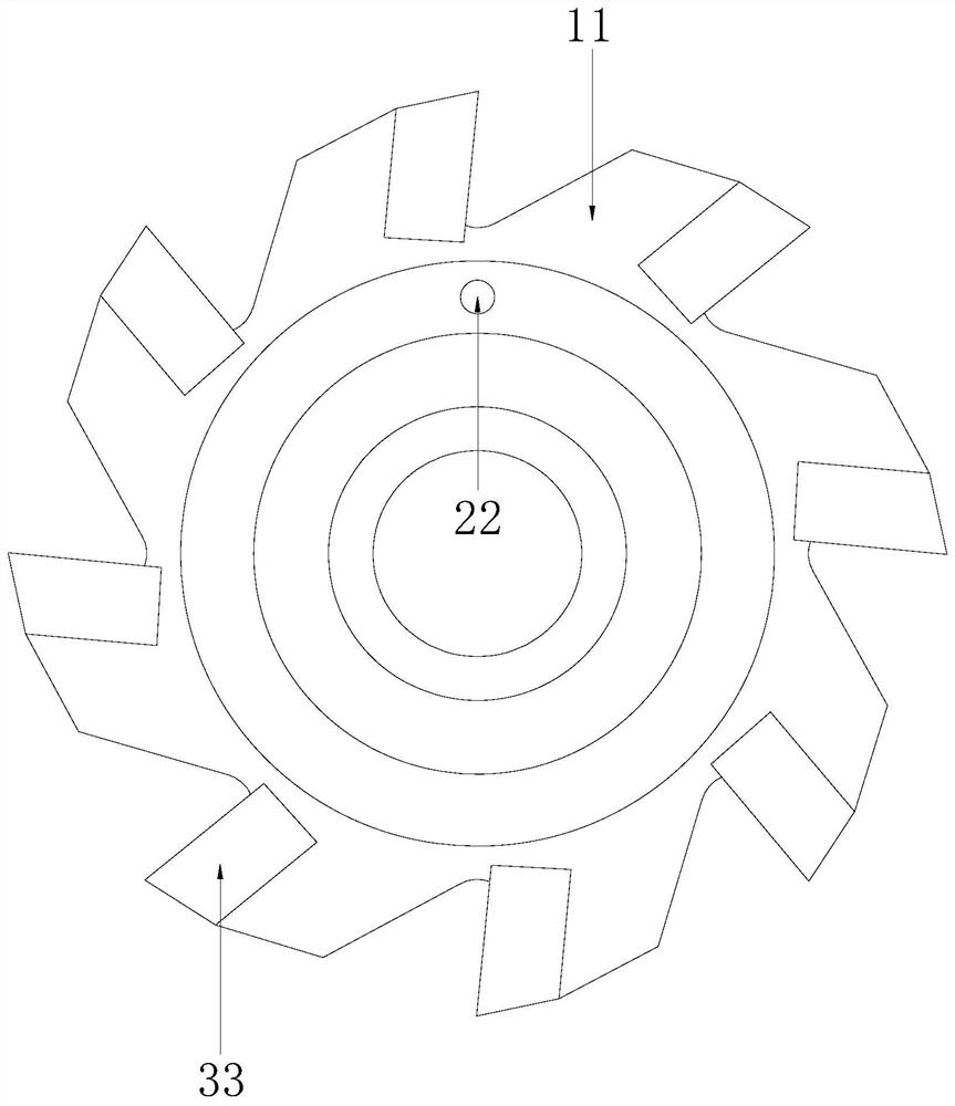
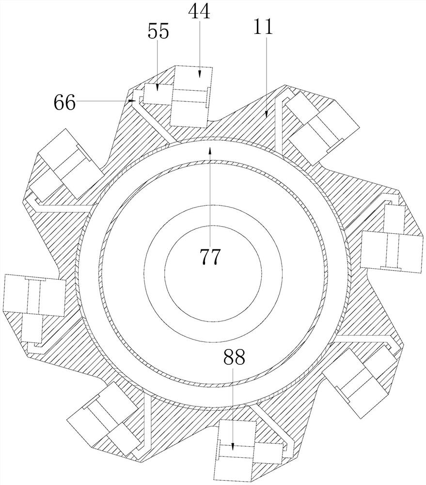
[0034] The milling cutter disc 4 includes a disc body 11, a liquid injection head 22, a milling cutter 33, a sipe 44, a limit clamping block 55, a runner 66, an annular cavity 77, and a bolt 88. Eight parts of the disc body 11 The equally divided positions are all provided with sipes 44, and the slits 44 are all placed with milling cutters 33, and the milling cutters 33 are connected with the limit clamping block 55 through bolts 88, and the limit clamping block 55 is connected w...


PUM


Abstract

The invention discloses a numerical control milling machine. The numerical control milling machine structurally comprises a machine body, a spindle box, a controller, a milling cutter head and a workbench. The controller is mounted outside the machine body and connected with the spindle box. The milling cutter head is mounted at the bottom of the spindle box. The workbench connected with the machine body is arranged below the milling cutter head. Compared with the prior art, the numerical control milling machine has the beneficial effects that the same thing is that milling cutters are fixed through bolts, and the different thing is that the bolts can also be clamped and fixed; the bolts are internally provided with clamping grooves and grooves, pistons are pushed to drive clamping blocksto clamp and fix the clamping grooves with injected cooling fluid as power, and the bolts are effectively prevented from getting loose due to the fact that the installation and rotating direction of bolt bodies is the same as the rotating direction of the milling cutter head and can also be protected against cracking due to the fact that the installation and rotating direction of the bolt bodies is opposite to the rotating direction of the milling cutter head; the stability of the milling cutters is further improved, and the machining precision of the milling cutters can be improved. Moreover,the cooling fluid can cool a cutter head body and the milling cutters to reduce the thermal wear degree of the milling cutters.

Description

technical field [0001] The invention relates to the technical field of numerical control machine tools, in particular to a numerical control milling machine. Background technique [0002] CNC milling machine comprehensively applies various technical achievements such as electronic computer, automatic control, servo drive, precision measurement and new mechanical structure. It has the functions of milling machine, boring machine and drilling machine, which makes the process highly concentrated and greatly improves production efficiency. [0003] The CNC milling machine needs to use the tool in the processing. The tool is installed on the cutter head. The cutter head is an important component of the CNC milling machine. However, the existing milling cutter and the cutter head are installed and fixed by bolts. If the installation and rotation of the bolts is in the same direction as the rotation of the cutter head, the long-term high-speed rotation of the cutter head and the fo...

Claims


Application Information

Patent Timeline
Patent Type & Authority Applications(China)
IPC IPC(8): B23C1/00B23Q11/10
CPCB23C1/00B23Q11/10
Inventor 曾群英
Owner 曾群英
Why Eureka
Try Eureka