A rotatable dump table

A technology of rotating material pouring and screw rod, applied in the field of material pouring table, can solve the problems of unable to realize automatic material pouring, unable to adjust the height of the material pouring table, etc., and achieve the effect of avoiding material scattering and reducing workload.

Active Publication Date: 2022-04-15
立宇食品(郎溪)有限公司
View PDF8 Cites 0 Cited by
  • Summary
  • Abstract
  • Description
  • Claims
  • Application Information

AI Technical Summary

Problems solved by technology

[0006] The purpose of the present invention is to provide a rotatable unloading platform to solve the problem of automatic unloading that cannot be mechanized in the above-mentioned background technology. The height adjustment of the material table and other issues

Method used


Image

  • A rotatable dump table
  • A rotatable dump table
  • A rotatable dump table

Examples


Embodiment Construction

[0022] The following will clearly and completely describe the technical solutions in the embodiments of the present invention with reference to the accompanying drawings in the embodiments of the present invention. Obviously, the described embodiments are only some, not all, embodiments of the present invention. Based on the embodiments of the present invention, all other embodiments obtained by persons of ordinary skill in the art without making creative efforts belong to the protection scope of the present invention.

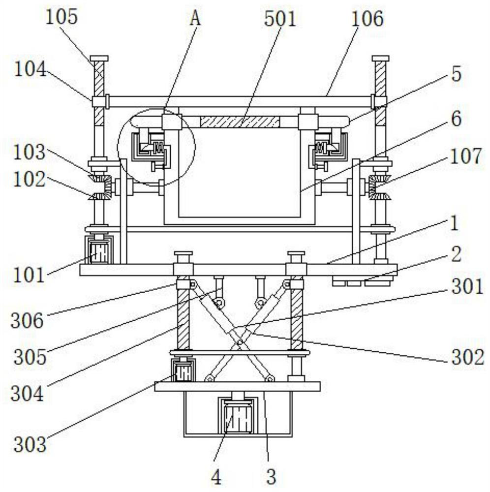
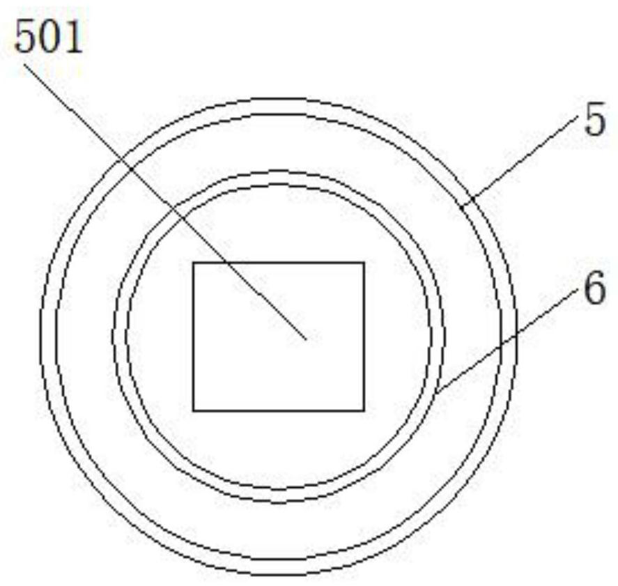
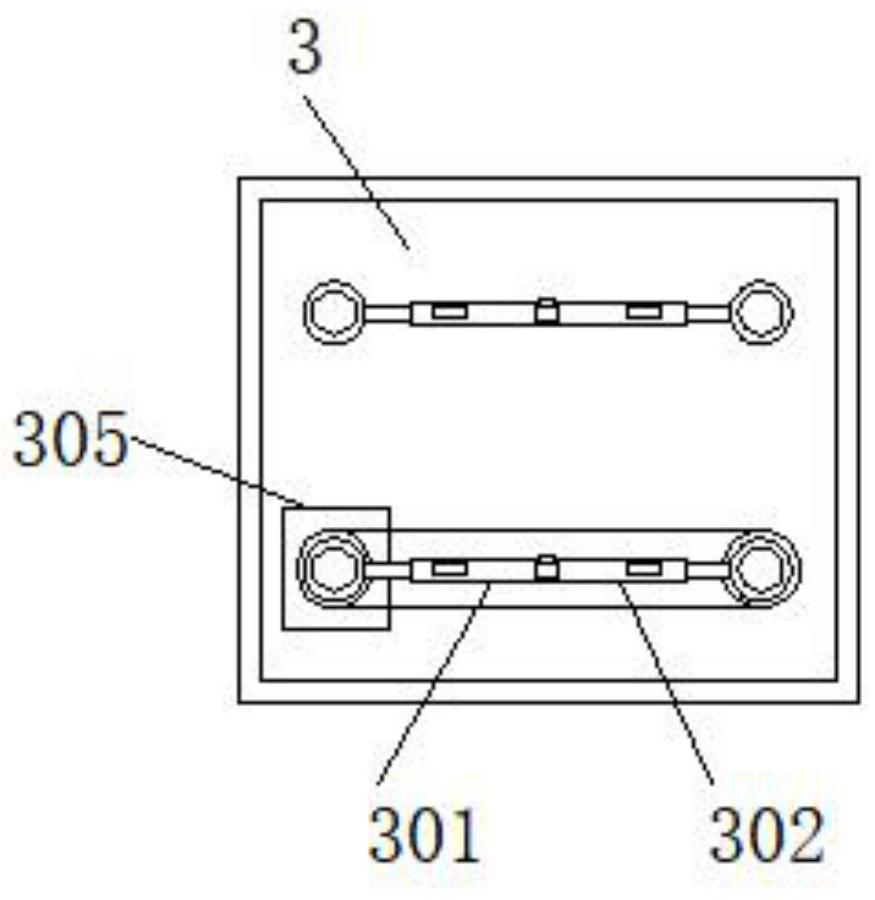
[0023] see Figure 1-4 , an embodiment provided by the present invention: a rotatable unloading platform, including a loading plate 1, a control panel 2 and a pressing cover 5, a first motor 101 is installed on one side of the top of the loading plate 1, and the first motor 101 The top of the top is fixedly connected with the first bevel gear 102, and one side of the top of the first bevel gear 102 is fixedly connected with the third bevel gear 107, and one si...


PUM


Abstract

The invention discloses a rotatable unloading platform, which comprises a bearing plate, a control panel and a pressing cover. A first motor is installed on one side of the top end of the bearing plate, and a control panel is installed on one side of the bottom end of the bearing plate. Both sides of the placement box are fixedly connected with a fixed block, and one side of the fixed block is provided with a second socket, and both sides of the bottom end of the pressing cover are fixedly connected with a connecting block, and the bottom end of the bearing plate is provided with a base plate, and a third motor is installed at the middle position of the bottom end of the base plate. The present invention uses the second motor installed on one side of the top of the bottom plate, the second motor will drive the second screw rod to rotate, and the second screw sleeve connected to the outside of the second screw rod can move up and down on the second screw rod, thereby driving The length of the first telescopic rod and the second telescopic rod changes, and the angle between the first telescopic rod and the second telescopic rod also changes, so that the support rod will drive the load plate to move up and down, so that the unloading table can be adjusted the height of.

Description

technical field [0001] The invention relates to the technical field of unloading tables, in particular to a rotatable unloading table. Background technique [0002] In industrial production and daily life, the transportation of materials is required. The materials need to be poured into the device or where they need to be used. In order to facilitate the operation of the operator during the discharge, a special discharge table will be used. Auxiliary unloading, the existing rotatable unloading table, there are still many problems in the process of use, the specific problems are as follows: [0003] 1. The existing rotatable unloading table cannot realize mechanized automatic unloading during use, and manual unloading on the unloading table is required, which increases the difficulty and workload of the work; [0004] 2. In the existing rotatable unloading table, during use, there is no structure to limit and fix the bagged raw materials on the unloading table, which is easy...

Claims


Application Information

Patent Timeline
Patent Type & Authority Patents(China)
IPC IPC(8): B65G65/23
CPCB65G65/23
Inventor 周平安简文崇
Owner 立宇食品(郎溪)有限公司
Why Eureka
Try Eureka