Brushless DC motor with improved ground structure

A technology of brushed DC motors and grounding components, which is applied in the direction of connection with grounding devices, electromechanical devices, and electrical components. The effect of electrolytic corrosion

Active Publication Date: 2020-09-25
NEW MOTECH
View PDF8 Cites 0 Cited by
  • Summary
  • Abstract
  • Description
  • Claims
  • Application Information

AI Technical Summary

Problems solved by technology

In the prior art, an effective ground connection is made between the upper and lower bearing caps, but since it has a structure that inserts the bearings outside the upper and lower bearing caps, the two bearings are easily exposed on the outside
In particular, due to

Method used


Image

  • Brushless DC motor with improved ground structure
  • Brushless DC motor with improved ground structure
  • Brushless DC motor with improved ground structure

Examples


Embodiment Construction

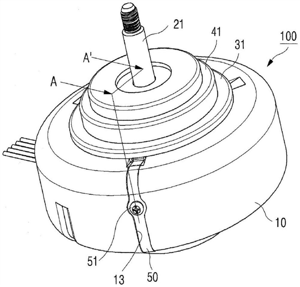
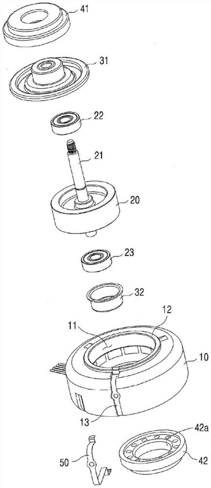
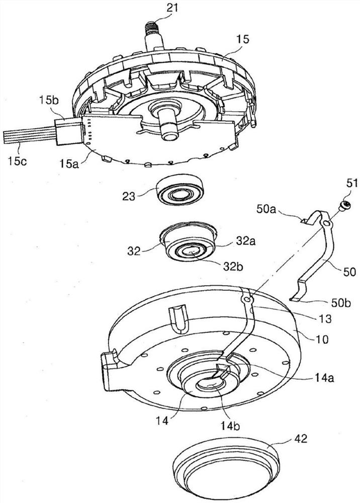
[0034] figure 1 It is an exploded view of the above motor 100 according to the present invention; figure 2 It is an exploded schematic diagram of the above motor 100 according to the present invention; image 3 It is an exploded schematic view of the bottom of the motor 100 according to the present invention.

[0035] From Figure 1 to Figure 3 It can be seen from the figure that the motor 100 according to the present invention may include a housing 10 , a rotor 20 , an upper bearing cover 31 , a lower bearing seat 32 , an upper protection member 41 and a lower protection member 42 .

[0036] The housing 10 has a hollow portion 11 in which a space in the middle is hollow, and an annular flange portion 12 protrudes upward along an upper portion of the hollow portion 11 . A rotor 20 coupled to and rotating with a shaft 21 is located within the hollow portion 11 . The first groove 13 is where the first ground member 50 is placed. The first groove 13 is formed by the flange ...


PUM


Abstract

The brushless DC motor according to the present invention, comprises: a housing 10 comprising a stator 15 in the inside, and having a hollow part 11 in which a rotor 20 coupled to a shaft 21 is positioned in the middle part; an upper bearing 22 coupled to an output side of the shaft 21 to rotatably support the shaft; an upper bearing cover 31 accommodating the upper bearing 22 and covering the hollow part 11; a lower bearing 23 coupled to a lower end of the shaft 21 to rotatably support the shaft; a lower bearing holder 32 accommodating the lower bearing 23 and coupled to a middle lower part of the housing 10; and a first grounding member 50 having an upper end part 50a bendingly coupled to an outer part of the upper bearing cover 31, and a lower end part 50b coupled to a middle part of the lower bearing holder 32, so as to make the upper bearing cover 31 and the lower bearing holder 32 electrically equipotential.

Description

technical field [0001] The invention relates to a grounding structure of an electric machine. More specifically, the present invention relates to a motor with a grounding structure. By improving the grounding structure, it can more effectively prevent electrolytic corrosion of bearings, improve performance and durability, and has the characteristics of small vibration and low noise. Background technique [0002] Generally, an electric machine includes a stator and a rotor. The rotor rotates under the influence of the magnetic field created by the stator. The shaft coupled to and rotating with the rotor has bearings to support the rotation of the shaft mounted above and below the rotor. [0003] Typically, such motors are controlled by drive circuits. When the drive circuit is running, the potential difference between the upper and lower bearings, or the axial current due to another cause, causes electrolytic corrosion of the bearings. When the motor is running under elec...

Claims


Application Information

Patent Timeline
IPC IPC(8): H02K11/40H02K7/08H02K5/173H02K29/00
CPCH02K11/40H02K5/1732H02K5/15H02K7/083H02K29/00
Inventor 李京柱梁玹诚姜玟硕
Owner NEW MOTECH
Why Eureka
Try Eureka