Wire arrangement device for reinforcing steel bars

A technology of wire arrangement and steel bar, applied in the field of steel wire arrangement, can solve the problem of low service life of guide rollers, and achieve the effect of reducing loss and speed difference

Inactive Publication Date: 2020-09-29
重庆黄朝物资有限公司
View PDF6 Cites 0 Cited by
  • Summary
  • Abstract
  • Description
  • Claims
  • Application Information

AI Technical Summary

Problems solved by technology

[0006] The purpose of the present invention is to provide a steel bar cable straightener, which can solve the problem of low service life of guide rollers

Method used


Image

  • Wire arrangement device for reinforcing steel bars

Examples


Embodiment 1

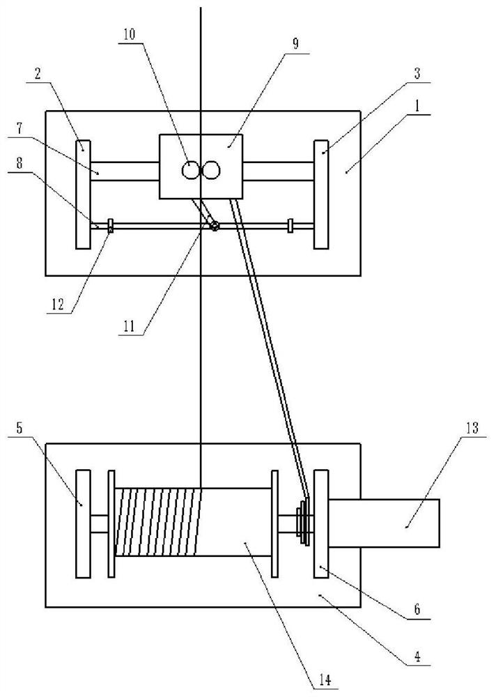
[0037] Such as figure 1 Shown, a kind of steel bar cable arrangement device comprises first frame, second frame, cable arrangement mechanism and I-shaped wheel 14 take-up mechanisms, leaves gap between the first frame and the second frame (this embodiment In the example, the distance between the two is 0.5m); wherein: the first frame includes the first base 1, the first left side plate 2 and the first right side plate 3, the first left side plate 2 and the first right side plate 3 are respectively welded on the left and right sides of the first base 1; the second frame includes the second base 4, the second left side plate 5 and the second right side plate 6, similarly, the second left side plate The side plates 6 are respectively welded and fixed on the left and right sides of the second base 4;

[0038] The cable arrangement mechanism includes a cable arrangement host 9, a guide shaft 7 and a stop guide rail 8. In this embodiment, the guide shaft 7 is a metal rod with a smo...

Embodiment 2

[0043] Compared with Embodiment 1, the only difference is that it also includes a limit rod. The top of the main body of the cable arrangement is welded with a left mounting block and a right mounting block. It is welded and fixed; it also includes a round tube, the limit rod runs through the round tube, and the round tube is connected to the limit rod in rotation; in other embodiments, in order to facilitate the adjustment of the upper and lower positions of the limit rod, the left and right mounting blocks are drilled There is a longitudinal slide rail, and a roller for moving in the slide rail is welded and fixed at both ends of the limit rod;

[0044] In addition, an infrared transmitter (model: SIR333) is bonded to the side of the left mounting block close to the limit rod. Similarly, an infrared receiver (model: LT0038) is fixedly bonded to the side of the right mounting block close to the limit rod. ); and the vertical height of the infrared receiver and the infrared em...


PUM


Abstract

The invention relates to the technical field of wire arrangement devices, in particular to a wire arrangement device for reinforcing steel bars. The wire arrangement device comprises a first rack, a second rack, a wire arrangement mechanism and a spool take-up mechanism. A gap is reserved between the first rack and the second rack. The first rack comprises a first base, a first left side plate anda first right side plate. The first left side plate and the first right side plate are fixed to the left side and the right side of the first base correspondingly. The second rack comprises a secondbase, a second left side plate and a second right side plate. The second left side plate and the second right side plate are fixed to the left side and the right side of the second base correspondingly. The wire arrangement mechanism comprises a wire arrangement device main machine, a guiding shaft and a stop block guide rail. The two ends of the guiding shaft are connected with the first left side plate and the first right side plate in a rotary manner correspondingly. The two ends of the stop block guide rail are fixedly connected with the first left side plate and the first right side plate. The guiding shaft is located at the upper end of the stop block guide rail. The guiding shaft penetrates the wire arrangement device main machine and is connected with the wire arrangement device main machine in a sliding manner. By means of the wire arrangement device, the problem that the service life of a guide roll is short can be solved.

Description

technical field [0001] The invention relates to the technical field of cable arranging devices, in particular to a steel bar arranging device. Background technique [0002] The I-shaped wheel take-up machine is to wind the finished steel wire drawn by the wire drawing machine onto the I-shaped wheel according to certain requirements. It is suitable for the quantification of coiled cold drawn wire, welding wire, cold rolled small flat steel, steel cable, etc. The coiling work is also suitable for coiling and bundling of cold-rolled ribbed steel bars. [0003] As an important part of the I-shaped wheel steel wire take-up machine, the wire straightener can guide the steel bars into the I-shaped wheel according to the required direction during the winding process, and arrange the steel bars at a certain pitch in the width direction; specifically, the wire straightener The working principle of the host, guide shaft and stopper guide rail is mainly to drive the host of the cable ...

Claims


Application Information

Patent Timeline
Patent Type & Authority Applications(China)
IPC IPC(8): B21C47/04
CPCB21C47/04
Inventor 程刚
Owner 重庆黄朝物资有限公司
Why Eureka
Try Eureka