Rotary stainless steel soup ladle stamping device

A kind of stamping equipment, stainless steel technology, applied in the field of rotary stainless steel spoon stamping equipment, can solve the problems of easy hand injury by the machine, low work efficiency, troublesome operation, etc., to achieve high work efficiency, convenient operation, and avoid injury Effect

Active Publication Date: 2020-09-29
揭阳市美钢五金塑胶制品有限公司
View PDF6 Cites 0 Cited by
  • Summary
  • Abstract
  • Description
  • Claims
  • Application Information

AI Technical Summary

Problems solved by technology

[0005] In order to overcome the disadvantages that the hand needs to move continuously and cooperate with the machine to stamp the stainless steel sheet into a stainless steel spoon, the operation is cumbersome, the work efficiency is low, and the hand is easily injured by the machine. The technical problem of the present invention is to provide a The operation and the machine cooperate to stamp stainless steel sheets into stainless steel spoons, which is convenient to operate, high in work efficiency, and a rotary stainless steel spoon punching equipment that is not easy to hurt the hands.

Method used


Image

  • Rotary stainless steel soup ladle stamping device
  • Rotary stainless steel soup ladle stamping device
  • Rotary stainless steel soup ladle stamping device

Examples


Embodiment 1

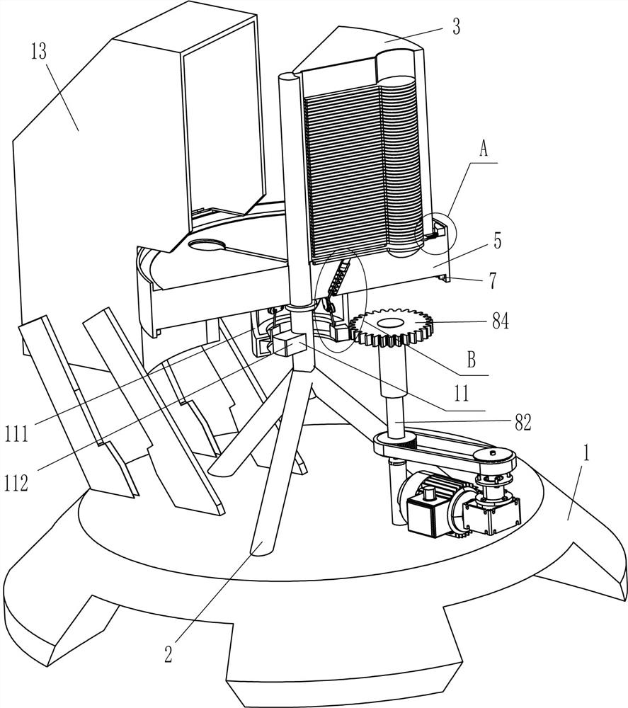
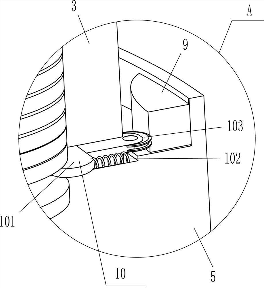
[0023] A rotary stainless steel spoon stamping equipment, such as Figure 1-Figure 3 As shown, it includes a base 1, a support rod 2, a blanking frame 3, a punching machine 4, a circular block 5, an inner ring gear 7, a driving mechanism 8, a bump 9 and a separation mechanism 10, and the top of the base 1 is fixed in the middle with a Strut 2, a blanking frame 3 is installed on the rear right side of the upper part of the strut 2, a partition mechanism 10 is provided on the lower rear side of the right side of the blanking frame 3, and a circular block 5 is connected to the lower part of the strut 2 in a circumferential rotation type The inner side of the circular block 5 is in contact with the bottom of the blanking frame 3, and the top of the circular block 5 is evenly spaced with three placement grooves 6. The placement grooves 6 cooperate with the blanking frame 3, and the upper part of the circular block 5 is evenly spaced circumferentially. There are three bumps 9 fixedl...

Embodiment 2

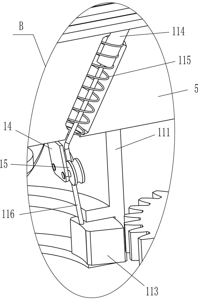
[0030] On the basis of Example 1, such as figure 2 and Figure 4 As shown, it also includes a pushing mechanism 11, and the pushing mechanism 11 includes an annular block 111, a strong magnet 112, an iron block 113, a push rod 114, a second spring 115 and a pull wire 116, and the circular block 5 bottoms are fixed at the center of the circle There is an annular block 111, and the support rod 2 is located in the annular block 111. Three iron blocks 113 are slidingly arranged on the lower part of the inner side of the annular block 111. A strong magnet 112 is fixedly connected to the front side of the lower part of the support rod 2. The strong magnet 112 and the iron block 113 Cooperate, place groove 6 bottom inner sliding type to be provided with push rod 114, be connected with second spring 115 between the bottom of push rod 114 and circular block 5 inside, push rod 114 bottom is also connected with backguy 116, and backguy 116 tails The end passes through the circular bloc...

Embodiment 3

[0033] On the basis of embodiment 1 and embodiment 2, such as figure 1 , figure 2 and Figure 4 As shown, it also includes a support plate 12 and a stop frame 13, two support plates 12 are fixed symmetrically front and back on the left side of the top of the base 1, and a stop frame 13 is installed between the top of the inner side of the four support plates 12, and the stop frame 13 and Circular block 5 fits.

[0034] It also includes a mounting plate 14 and a wire pulley 15. Three mounting plates 14 are fixedly spaced evenly in the middle of the bottom of the circular block 5 in the circumferential direction. The mounting plate 14 corresponds to the pull wire 116, and the lower part of the outer surface of the mounting plate 14 rotates symmetrically. Type is connected with guide wheel 15, and every backguy 116 passes between corresponding two guide wheels 15 and cooperates with it.

[0035] Firstly, the operator places the collection container under the stop frame 13. Wh...


PUM


Abstract

The invention relates to stamping equipment, and particularly relates to a rotary stainless steel soup ladle stamping device. The rotary stainless steel soup ladle stamping device aims to achieve thetechnical effects that manual operation is not needed, the equipment can be matched with a machine to stamp stainless steel sheets into stainless steel soup ladles, operation is convenient, the working efficiency is high, and hands are not prone to being injured. The rotary stainless steel soup ladle stamping device comprises a base, wherein a supporting rod is installed in the middle of one sideof the base; and a discharging frame is fixedly connected to the side, far away from the base, of the supporting rod. According to the rotary stainless steel soup ladle stamping device, a proper number of stainless steel sheets are placed in the discharging frame, a servo motor is started to rotate forwards, then a circular block can rotate forwards to drive the stainless steel sheets to rotate forwards by 120 degrees through a containing groove, then a stamping machine is started to stamp the stainless steel sheets into the stainless steel soup ladles, and therefore the hands of an operator do not need to be used continuously, operation is convenient, the working efficiency is high, and the hands can be prevented from being injured.

Description

technical field [0001] The invention relates to stamping equipment, in particular to a rotary stainless steel spoon stamping equipment. Background technique [0002] Soup ladle, a utensil for ladle soup, in the production process of the soup ladle, most of the processed stainless steel sheet is stamped into a stainless steel soup ladle. [0003] At present, most of the stainless steel sheets are stamped into stainless steel spoons through the cooperation of people and machines. First, the machine needs to be started, and then moved to the machine by hand to be punched into stainless steel spoons, and then the stainless steel spoons are removed and replaced with stainless steel sheets. Stamping again, so repeated, the operation is more troublesome, the work efficiency is low, and people need to constantly move around the machine, which is easy to be injured by the machine. [0004] Therefore, there is a special need for a rotary stainless steel spoon punching equipment that ...

Claims


Application Information

Patent Timeline
Patent Type & Authority Applications(China)
IPC IPC(8): B21D53/62B21D43/00B21D43/24B21D45/02B21D43/20
CPCB21D53/62B21D43/003B21D43/24B21D45/02B21D43/20
Inventor 王生平
Owner 揭阳市美钢五金塑胶制品有限公司
Why Eureka
Try Eureka