Combined anti-collision guardrail structure

A technology of anti-collision guardrails and combined structures, applied in roads, road safety devices, roads, etc., can solve the problem of limited deformation capacity and energy absorption capacity of guardrails, limited deformation capacity and energy absorption capacity, and safety issues of vehicles and crew members. In order to achieve the effect of overall structural coordination, good connection performance, reduced energy exchange, and improved car body safety performance

Pending Publication Date: 2020-09-29
沈阳促晋科技有限公司
View PDF0 Cites 0 Cited by
  • Summary
  • Abstract
  • Description
  • Claims
  • Application Information

AI Technical Summary

Problems solved by technology

At present, the existing guardrails on the market do not have the function of cushioning and shock absorption when they are in use. When a car hits the guardrail, it can only rely on the deformation of the guardrail to damage the energy absorption, and the deformation and energy absorption capabilities are limited.
And the guardrail board is easy to break under the impact of the car, causing the guardrail to be unable to use normally, and it is also easy to cause secondary damage to the safety of the vehicle and the crew. In summary, how to solve the deformation ability and energy absorption of the existing highway guardrail The problem of limited ability has become a problem that those skilled in the art need to solve

Method used


Image

  • Combined anti-collision guardrail structure
  • Combined anti-collision guardrail structure
  • Combined anti-collision guardrail structure

Examples


Embodiment Construction

[0026] The present invention will be described in detail below in conjunction with the implementations shown in the drawings, but it should be noted that these implementations are not limitations of the present invention, and those of ordinary skill in the art based on the functions, methods, or structural changes made by these implementations Equivalent transformations or substitutions all fall within the protection scope of the present invention.

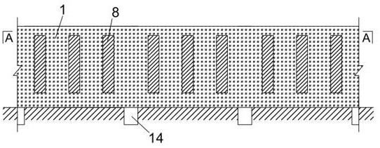
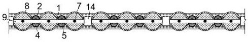
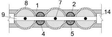
[0027] Such as Figure 1-10 As shown, the present invention provides a combined crash barrier structure, including a crash pad 1, an energy-dissipating extrusion combined structure 2, an arc-shaped thin-walled energy-dissipating steel plate 3, an energy-dissipating filling material 4, a connector 5, a connecting Plate 6, connecting fixed rod 7, rotating anti-collision barrel 8, connecting beam 9, inner cylinder 10, anti-collision, shock-absorbing and energy-consuming material layer 11, hollow area 12, anti-collision soft outer cyl...


PUM


Abstract

The invention discloses a combined anti-collision guardrail structure, which belongs to the technical field of road traffic facilities. The combined anti-collision guardrail structure comprises an anti-collision pad, an energy consumption extrusion combined structure, an arc-shaped thin-wall energy consumption steel plate, an energy consumption filling material, a connecting piece, a connecting plate, a connecting fixing rod, a rotating anti-collision barrel, a connecting cross beam, an inner barrel, an anti-collision damping energy consumption material layer, a hollow area, an anti-collisionsoft outer barrel, a vertical connecting fixing pile and an energy consumption extrusion cavity. When the vehicle body collides with the guardrail, the vehicle body can be forced to change the direction, the installation operation is remarkably simplified, the assembly speed is high, the industrialization process is promoted, the anti-collision and shock absorption coordinated energy dissipation capacity is high, the collision force can be fully dissipated, and the anti-collision pad can play a role in buffering and protecting. By means of the energy consumption extrusion combined structure, the energy consumption filling material, the anti-collision damping energy consumption material and the anti-collision soft outer cylinder, damping energy consumption can be conducted, impact force canbe greatly buffered, and the multiple damping effect is achieved.

Description

technical field [0001] The invention belongs to the technical field of road traffic facilities, in particular to a combined anti-collision guardrail structure. Background technique [0002] With the development of the national economy, a large number of roads and expressways have been built or are under construction. At present, the guards on both sides of the expressway and the road are made up of columns and a guard plate positioned on its top, and the guard plate is made of steel plates, both of which are rigid materials and are rigidly connected. When the car loses control and hits the protective plate, the protective device can prevent the car from turning into the waterproof ditch on both sides of the expressway or rushing into the opposite lane to crash. But practice has proved that the protective plate of the above structure has no cushioning function. Under the high-speed and powerful impact of an out-of-control car, the protective plate will often be broken. Peop...

Claims


Application Information

Patent Timeline
IPC IPC(8): E01F15/02E01F15/08
CPCE01F15/02E01F15/081E01F15/088
Inventor 张延年杨森
Owner 沈阳促晋科技有限公司
Why Eureka
Try Eureka