Fixing frame for testing infrared detector
An infrared detector and fixing frame technology, applied in the field of infrared detectors, can solve the problems of inconvenient installation, inflexible infrared detector testing, troublesome installation and disassembly, etc.
- Summary
- Abstract
- Description
- Claims
- Application Information
AI Technical Summary
Problems solved by technology
Method used
Image
Examples
Embodiment 1
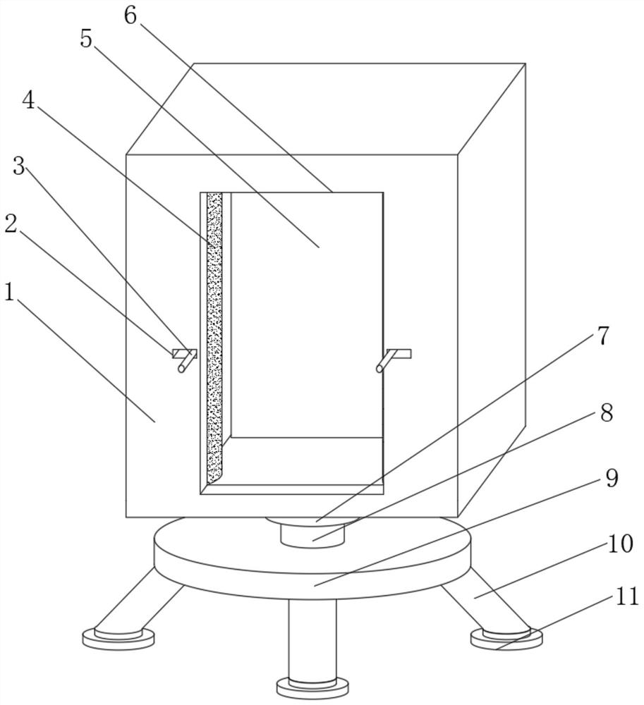
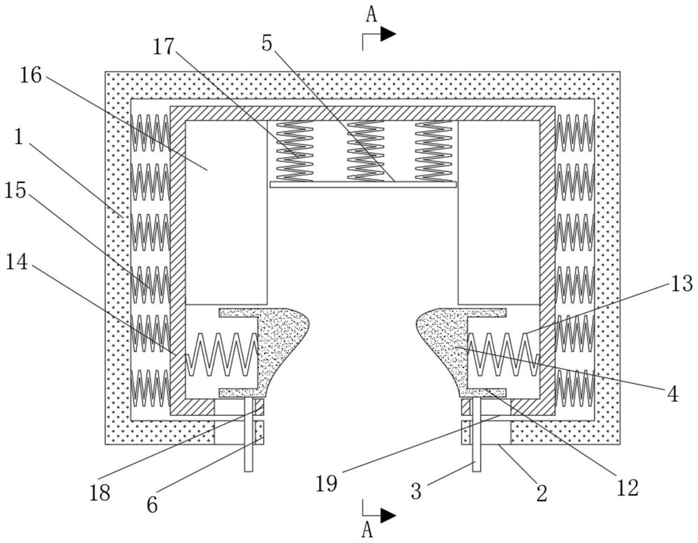
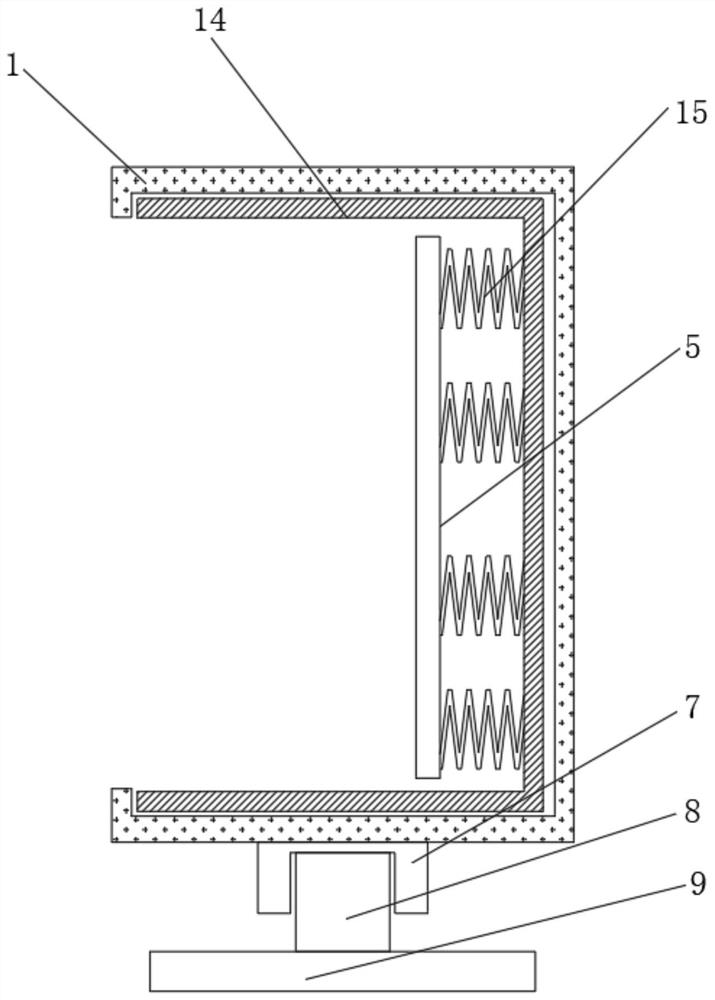
[0029] refer to Figure 1-3 , a fixed frame for infrared detector testing, comprising an outer shell 1 and an inner shell 14, one side of the outer shell 1 is provided with a shell through groove 6, and the inner walls of both sides of the outer shell 1 are fixedly equipped with a plurality of second return springs 15, and a plurality of One end of the second return spring 15 is fixedly connected with the outer wall of the inner shell 14, and both sides of the inner wall of the inner shell 14 are fixedly equipped with fixed blocks 16, and both sides of the inner wall of the inner shell 14 are fixedly equipped with the first return spring 13, Between one side of the fixed block 16 and one side of the inner wall of the inner shell 14, a sliding clamping column 4 is movably installed, and one side of the sliding clamping column 4 is provided with a groove 12. The inner wall of the groove 12 is fixedly connected, and one side of the inner shell 14 is provided with an inner shell t...
Embodiment 2
[0033] refer to Figure 4-6 , a fixed frame for infrared detector testing, further comprising three fixed bases 11 below which are provided with slots 24, and the bottoms of the three fixed bases 11 are clamped with second support rods 20 through the slots 24, and the second support rods The bottom of 20 is fixedly installed with metal triangular cone 22, and the bottom side of second support rod 20 is fixedly installed with rubber telescopic rope 21, and one end of rubber telescopic rope 21 is fixedly installed with the protective cover 23 that matches with metal triangular cone 22 , The protective cover 23 is made of rubber material.
[0034]During use, the second support rod 20, the rubber telescopic rope 21, the metal triangular cone 22, the protective cover 23, the draw-in groove 24 are set, and the first support rod 20 can improve the stability of the fixed frame by snapping the second support rod 20 through the draw-in groove 24. height, and through the metal triangula...
PUM
 Abstract
Description
Claims
Application Information
 - R&D
- Intellectual Property
- Life Sciences
- Materials
- Tech Scout
- Unparalleled Data Quality
- Higher Quality Content
- 60% Fewer Hallucinations
Browse by: Latest US Patents, China's latest patents, Technical Efficacy Thesaurus, Application Domain, Technology Topic, Popular Technical Reports.
© 2025 PatSnap. All rights reserved.Legal|Privacy policy|Modern Slavery Act Transparency Statement|Sitemap|About US| Contact US: help@patsnap.com


