
Laser cutting module and device

A technology of laser cutting and laser cutting head, which is applied in the direction of laser welding equipment, metal processing equipment, welding equipment, etc., can solve the problems of reduced production efficiency, poor roundness, and decreased roundness of round holes, so as to improve efficiency and cut Effects of improved accuracy and reduced rotational range

Active Publication Date: 2020-10-02
SUZHOU PRESSLER ADVANCED FORMING TECHNOLOGIES CO LTD
View PDF6 Cites 2 Cited by
  • Summary
  • Abstract
  • Description
  • Claims
  • Application Information

AI Technical Summary

Problems solved by technology

When the cutting speed is too fast, the movement synchronization of the motors involved in the movement and its mechanical parts will have a slight deviation, which will cause the cutting path to be different from the envisaged path, so that the roundness of the round hole after cutting will be different. Decline, especially when the diameter of the cut arc or hole is small (usually refers to the diameter is less than 30mm), the phenomenon of poor roundness is particularly obvious
At present, the method of cutting at reduced speed is often used to ensure the roundness of the arc and the round hole, so that the product can meet the standard, but the production efficiency is also greatly reduced.

Method used


Image

  • Laser cutting module and device
  • Laser cutting module and device
  • Laser cutting module and device

Examples


Embodiment Construction

[0037] The following will clearly and completely describe the technical solutions in the embodiments of the present invention with reference to the accompanying drawings in the embodiments of the present invention. Obviously, the described embodiments are only some, not all, embodiments of the present invention. Based on the embodiments of the present invention, all other embodiments obtained by persons of ordinary skill in the art without making creative efforts belong to the protection scope of the present invention.

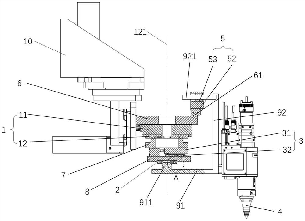
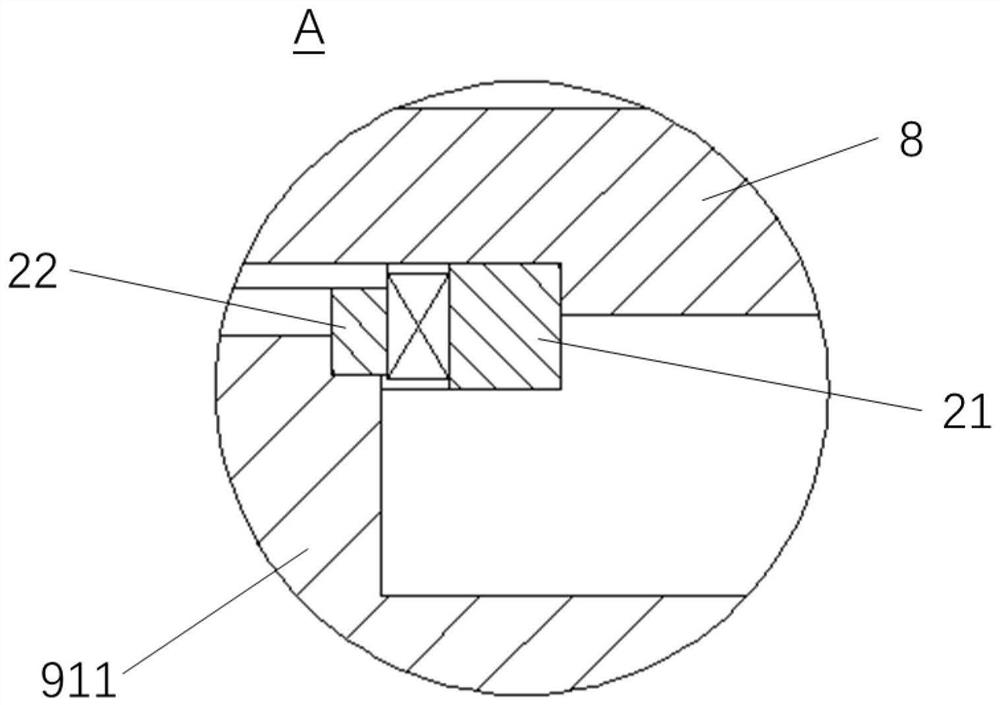
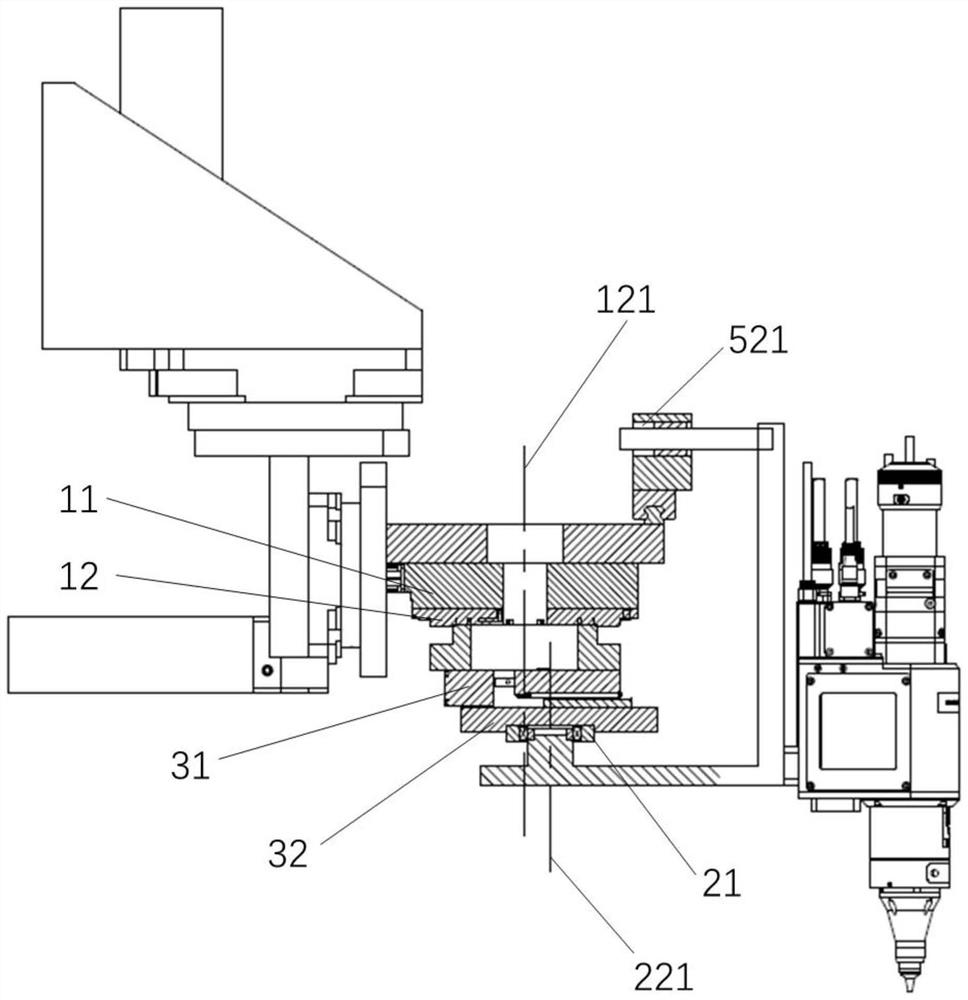
[0038] combine Figures 1 to 3 as well as Figure 7 As shown, the laser cutting device in this embodiment includes a machine tool 10 and a laser cutting module installed on the machine tool 10. Driven by the motor, the laser cutting module can move along the X-axis, Y-axis and Z-axis directions of the machine tool 10. Translate to move to a specific position to laser cut the workpiece. The laser cutting device can be used for cutting arcs or circular holes w...


PUM


Abstract

The invention discloses a laser cutting module and device. The laser cutting module comprises a first rotating mechanism, a second rotating mechanism, a laser cutting head and a guiding piece; the first rotating mechanism is provided with a first fixed part and a first movable part which are rotationally connected, the second rotating mechanism is provided with a second fixed part and a second movable part which are rotationally connected, the second fixed part can be arranged on the first movable part in a sliding mode in the first moving direction, and when the device cuts an arc, the firstmovable part can drive the second fixed part to rotate, the second movable part can rotate relative to the second fixed part, and rotating shafts of the first movable part and the second movable partdo not coincide; the laser cutting head is fixedly connected to the second movable part; and the guiding piece can guide the laser cutting head in two directions which are not parallel to the rotatingshaft of the first movable part at the same time so as to limit the rotation of the laser cutting head, and an included angle between the two directions is larger than 0 degree and smaller than 180 degrees. The scheme has the advantages that the cutting precision is ensured and the cutting efficiency is improved under the condition that the cutting speed is not reduced.

Description

technical field [0001] The invention relates to the field of laser cutting, in particular to a laser cutting module and device. Background technique [0002] In the existing laser cutting process, when cutting round holes and arcs, it usually relies on five-axis interpolation or two-axis interpolation to realize the cutting of round holes and arcs on the plane. Two-axis interpolation methods include: the laser cutting head moves simultaneously along the XY axis of the machine tool to form a circular arc or circular hole at a specific speed and trajectory; five-axis interpolation methods include: three-dimensional circular holes and circular arcs The laser cutting head moves together along the five axes of X, Y, Z, A, and C of the machine tool to form a three-dimensional arc or circular hole at a specific speed and trajectory. [0003] The disadvantage of the existing interpolation cutting is that since each axial interpolation is driven by a corresponding motor, the number ...

Claims


Application Information

Patent Timeline
IPC IPC(8): B23K26/08B23K26/38B23K26/70
CPCB23K26/0884B23K26/38B23K26/702
Inventor 胡剑峰安健王波
Owner SUZHOU PRESSLER ADVANCED FORMING TECHNOLOGIES CO LTD
Learn More