
A welding jig

A welding fixture and hinged technology, which is applied in welding equipment, auxiliary welding equipment, welding/cutting auxiliary equipment, etc., can solve problems such as scratches on the workpiece surface, burning of the positioning wheel, and affecting product quality, so as to ensure that the weld seam is full, The effect of reliable clamping

Active Publication Date: 2020-11-24
BICHAMP CUTTING TECH (HUNAN) CO LTD
View PDF10 Cites 0 Cited by
  • Summary
  • Abstract
  • Description
  • Claims
  • Application Information

AI Technical Summary

Problems solved by technology

[0003] Currently used welding fixtures, such as the patent announcement number CN209867806U, disclose a welding fixture. The fixture is in surface contact with the workpiece. Because the workpiece is soft, the fixture hardness is high, and the welding material is floating up and down, which often causes scratches on the surface of the workpiece or be damaged. If it is stuck, the positioning wheel will be burned and scrapped during welding, which will also affect the product quality.

Method used


Image

  • A welding jig
  • A welding jig
  • A welding jig

Examples


Embodiment Construction

[0026] The present invention will be described in detail below with reference to the accompanying drawings and examples. It should be noted that, in the case of no conflict, the embodiments of the present invention and the features in the embodiments can be combined with each other. For the convenience of description, if the words "up", "down", "left" and "right" appear in the following, it only means that the directions of up, down, left and right are consistent with the drawings themselves, and do not limit the structure.

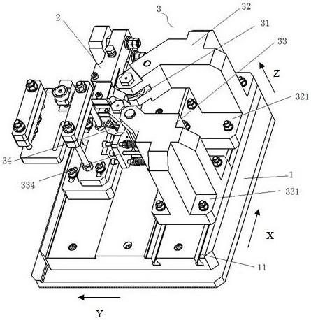
[0027] Such as figure 1 As shown, a welding fixture provided in this embodiment includes a base 1 and a clamping mechanism 2 and a positioning mechanism 3 arranged on the base 1 .

[0028] Set the length direction of the base 1 as the X direction, the width as the Y direction, and the height as the Z direction. One end of the base 1 in the Y direction is provided with a plurality of first mounting holes (not shown), and the other end is provided with a ...


PUM


Abstract

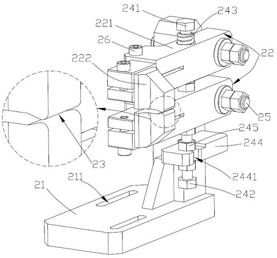
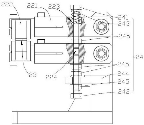
The invention provides a welding clamp. The welding clamp comprises a first base and two camping arms which are arranged opposite to each other up and down; one end of each of the two clamping arms are hinged to the first base; the hinged axis line is arranged horizontally; the clamping arms rotate around hinged axis line and are locked through a locking mechanism; the other ends of the two clamping arms form a clamping cavity through arranged convex edge structures; the up-down dimension of the clamping cavity is adjusted through the locking mechanism; a positioning mechanism comprises a first positioning mechanism, a second positioning mechanism, and guide wheels which are arranged on the first positioning mechanism and the second positioning mechanism; and the guide wheels get close tothe clamping cavity and the axis lines of the guide wheels are arranged vertically. Compared with the prior art, the welding clamp provided by the invention can realize reliable clamping so as to ensure poor quality of up-down dislocation in a welding process.

Description

technical field [0001] The invention relates to the technical field of band saw blade processing, in particular to a welding fixture. Background technique [0002] The production process of the band saw blade is that the back material and the high-speed steel wire are made into a composite steel strip by means of laser welding or electron beam welding, and then the front end of the high-speed steel wire is milled into the shape of the tip of the tooth through the tooth milling process. The sandblasting process is the final shape. Welding fixtures are usually required in strip-to-wire welding. [0003] Currently used welding fixtures, such as the patent announcement number CN209867806U, disclose a welding fixture. The fixture is in surface contact with the workpiece. Because the workpiece is soft, the fixture hardness is high, and the welding material is floating up and down, which often causes scratches on the surface of the workpiece or be damaged. If it is stuck, the pos...

Claims


Application Information

Patent Timeline
Patent Type & Authority Patents(China)
IPC IPC(8): B23K37/04
CPCB23K37/0443
Inventor 李栋梁
Owner BICHAMP CUTTING TECH (HUNAN) CO LTD
Learn More