
Method for characterizing planar energy differences of leading-edge single sand layer

A technology of energy difference and plane, applied in the field of oilfield reservoir research, it can solve problems such as unbalanced effects, and achieve the effects of fine classification, clear inter-well connectivity, and strong operability

Active Publication Date: 2020-10-02
PETROCHINA CO LTD +1
View PDF10 Cites 0 Cited by
  • Summary
  • Abstract
  • Description
  • Claims
  • Application Information

AI Technical Summary

Problems solved by technology

[0005] The technical problem to be solved by the present invention is to overcome the problem existing in the background technology that when a large-area sheet-shaped development block of thin-bed sand enters the late stage of high water cut due to the change of planar seepage energy, the problem of unbalanced effect is prominent, and to provide a kind of former The plane energy difference characterization method of the front single sand layer, the front single sand layer plane energy difference characterization method, improves the understanding of the plane heterogeneity characteristics of the front single sand layer, and is suitable for the analysis of the connectivity relationship of medium and low permeability reservoirs

Method used


Image

  • Method for characterizing planar energy differences of leading-edge single sand layer
  • Method for characterizing planar energy differences of leading-edge single sand layer
  • Method for characterizing planar energy differences of leading-edge single sand layer

Examples


Embodiment 1

[0032] Using the method for characterization of the energy difference in the plane of the front single sand layer described in the present invention, the implementation process of the method of the present invention is illustrated by taking the eastern part of the pure oil area of ​​the Xingshi District of Daqing Oilfield as an example.

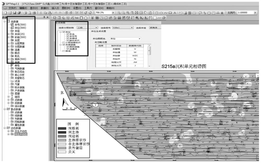
[0033] Step (1) Collect the sedimentary unit stratification boundary database, well location coordinate database, well deviation data, stratification database and production well logging curve vector data, use the GPTmap reservoir automatic drawing software to load data, through the stratification boundary facies type and Connectivity calculation, the software automatically generates the random facies diagram of each sedimentary unit (see attached figure 1 );

[0034] Step (2) On the basis of the random facies belt map of the sedimentary unit in step (1), select the facies belt base map of the sedimentary unit with a large area of ​​thin-bed ...


PUM


Abstract

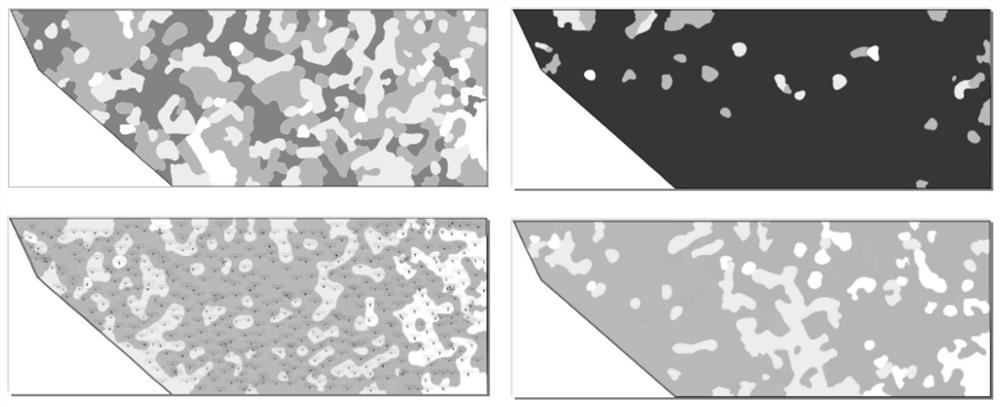
The invention relates to a method for characterizing planar energy differences of a leading-edge single sand layer. The problem that for a thin-layer sand large-area mat-shaped development block, dueto the change of the planar seepage energy, the effect disequilibrium contradiction is prominent is mainly solved. The method comprises the following steps that 1) an oil reservoir automatic drawing software is utilized for automatically generating a random phase band diagram of each deposition unit; 2) a coring-well core comprehensive diagram is utilized for analyzing lithology and a logging curve difference, an energy micro-phase logging mode is established, single sand layer lithological physical property parameters are counted by using a hierarchical database, a histogram is made, all energy micro-phase distribution intervals are determined, and an energy micro-phase classification standard is established by combining the energy micro-phase logging mode; 3) deposition-unit random phaseband diagrams with energy micro-phase changes are regenerated; and 4) man-machine interaction is used for drawing a phase band diagram with planar energy attenuation changes of the single sand layer,and the single sand layer is classified into four sand body types. The characterization method improves the recognition of the planar non-homogeneous features of the leading-edge single sand layer, and is suitable for medium and low permeability reservoir communication relationship analysis.

Description

technical field [0001] The invention relates to the technical field of oilfield reservoir research, in particular to a method for characterizing the plane energy difference of a front single sand layer. Background technique [0002] The front single sand layer refers to the sand layer that has been subdivided into the smallest sedimentary unit in the vertical direction, and has the characteristics of single and stable horizon, flat sand body sheet distribution, and traceability. It is the main object of secondary and tertiary infill water flooding development in the oilfield. After years of water injection development, although the overall production thickness reaches 82.4%, after entering the high water cut period, the contact relationship between single layers is relatively good on the surface, but the effect results The difference is large, and the plane seepage law of sand bodies is unclear, which increases the difficulty of remaining oil analysis and measure adjustment....

Claims


Application Information

Patent Timeline
Patent Type & Authority Applications(China)
IPC IPC(8): E21B49/00G06F30/20
CPCE21B49/00G06F30/20Y02A10/40
Inventor 苗厚纯杨为华赵红张灵芝孟丽丽韩沛辰
Owner PETROCHINA CO LTD
Learn More