Woodworking center marking and perforating device
A punching device and punctuation technology, applied in manufacturing tools, workshop equipment, etc., can solve problems such as labor consumption, and achieve the effect of improving stability, accuracy, and uniformity.
- Summary
- Abstract
- Description
- Claims
- Application Information
AI Technical Summary
Problems solved by technology
Method used
Image
Examples
Embodiment 1
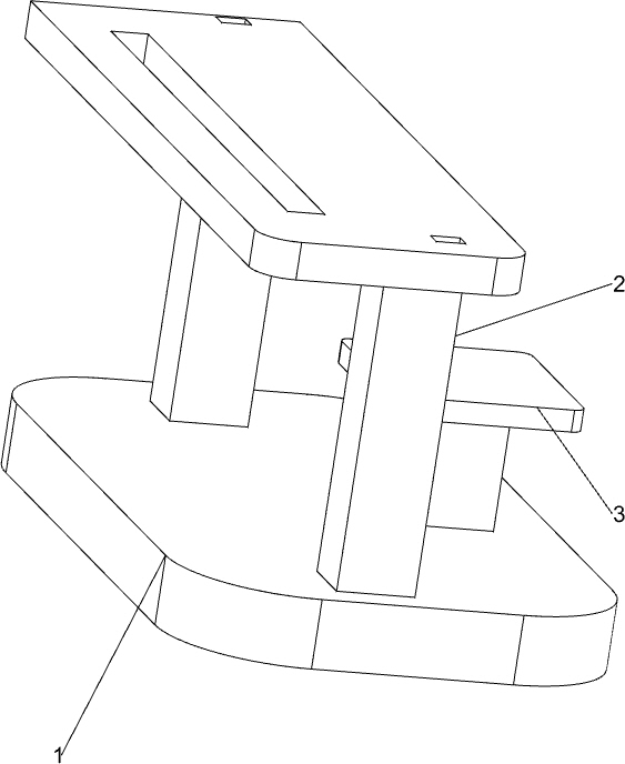
[0055] A woodworking center punctuation punching device, such as Figure 1-3 As shown, it includes a base 1, a workbench 2, a support platform 3, a transmission mechanism 4 and a feeding mechanism 5. The front side of the top of the base 1 is connected to the workbench 2, and the middle of the rear side of the top of the base 1 is provided with a support platform 3. The support platform 3 A transmission mechanism 4 is connected between the top and the workbench 2, and a feeding mechanism 5 is connected to the back of the workbench 2.
[0056] When people need to punctuate the center of the timber, the timber is first placed on the feeding mechanism 5, and then the transmission mechanism 4 is started. In the parts, the wood is punctuated by the center, and the wood is taken out after the punctuation is completed. When it is not necessary to punctuate the wood, the transmission mechanism 4 can be closed.
Embodiment 2
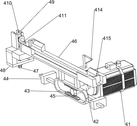
[0058] On the basis of Example 1, such as Figure 4 , 6, 8, the transmission mechanism 4 includes a motor 41, a shaft sleeve 42, a missing gear 43, a mounting block 44, a gear sleeve 45, a moving mold 46, a threaded rod 47, a support seat 48, a slide rail 49, a slide block 410, a punctuation point Device 411, first spring 412, connection block 413, wedge block 414 and push plate 415, support table 3 top is connected with motor 41, is connected with axle sleeve 42 on the output shaft of motor 41, is connected with missing gear 43 on the axle sleeve 42, The middle parts of the left and right sides of the front part of the workbench 2 are connected with a mounting block 44, and a gear sleeve 45 is slidably connected between the mounting blocks 44. The upper and lower sides of the gear sleeve 45 can be meshed with the missing gear 43. There is a slot, the top of the gear sleeve 45 is connected with a movable mold 46, the movable mold 46 is slidingly connected with the workbench 2...
Embodiment 3
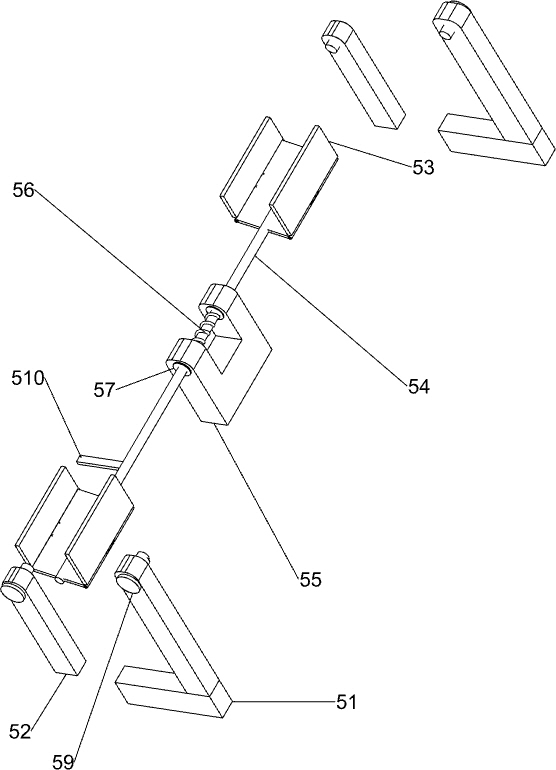
[0061] On the basis of Example 2, such as Figure 5-7 As shown, the feeding mechanism 5 includes a first support frame 51, a second support frame 52, a movable connecting plate 53, a first connecting rod 54, a support block 55, a torsion spring 56, a movable bolt 57, a feeding plate 58 and a rotating Shaft 59, the left and right sides of the top rear side of the workbench 2 are connected with the second support frame 52, the left and right sides of the workbench 2 rear wall are connected with the first support frame 51, the first support frame 51 and the second support frame 52 The tops are all connected with rotating shafts 59, and between the rotating shafts 59 are connected a feeding plate 58. A support block 55 is provided in the middle of the rear side of the top of the workbench 2. The top of the support block 55 is rotatably connected with a first connecting rod 54. A torsion spring 56 is connected between the rod 54 and the support block 55, and the torsion spring 56 i...
PUM
 Abstract
Description
Claims
Application Information
 - R&D
- Intellectual Property
- Life Sciences
- Materials
- Tech Scout
- Unparalleled Data Quality
- Higher Quality Content
- 60% Fewer Hallucinations
Browse by: Latest US Patents, China's latest patents, Technical Efficacy Thesaurus, Application Domain, Technology Topic, Popular Technical Reports.
© 2025 PatSnap. All rights reserved.Legal|Privacy policy|Modern Slavery Act Transparency Statement|Sitemap|About US| Contact US: help@patsnap.com


