Washing machine
A washing machine and housing technology, applied in the field of washing machines, can solve the problems of complex structure and increased cost, and achieve the effect of ensuring communication performance and good communication performance
- Summary
- Abstract
- Description
- Claims
- Application Information
AI Technical Summary
Problems solved by technology
Method used
Image
Examples
Embodiment approach 1
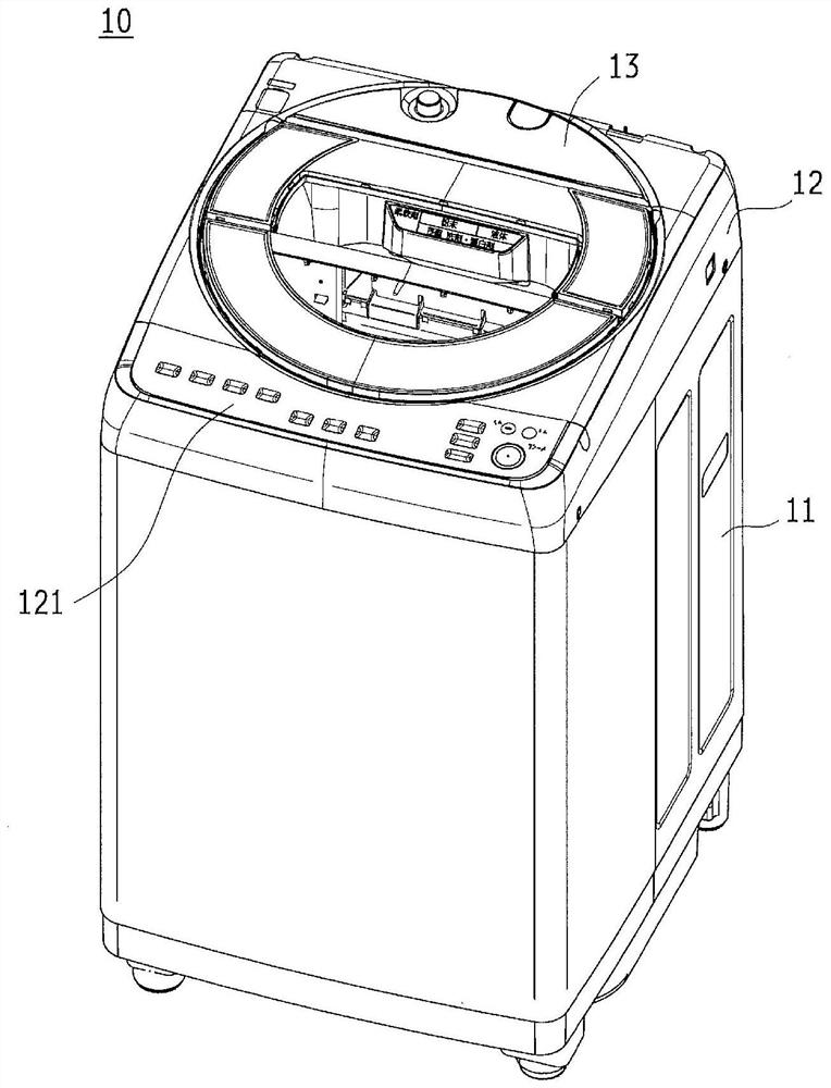
[0030] Embodiments of the present invention will be described in detail below with reference to the accompanying drawings. figure 1 It is a perspective view showing the appearance of washing machine 10 according to the first embodiment. Such as figure 1 As shown, the appearance of the washing machine 10 is composed of a lower case 11 , an upper case 12 , and a cover 13 constituting a main body case of the washing machine 10 .
[0031] The lower case 11 forms most of the main body case and is configured as a case made of metal. The upper case 12 is arranged above the lower case 11 and is configured as a case made of resin. The cover body 13 is attached to the upper surface of the upper casing 12 and is provided so as to openably and closably cover the laundry inlet on the upper surface of the upper casing 12 .
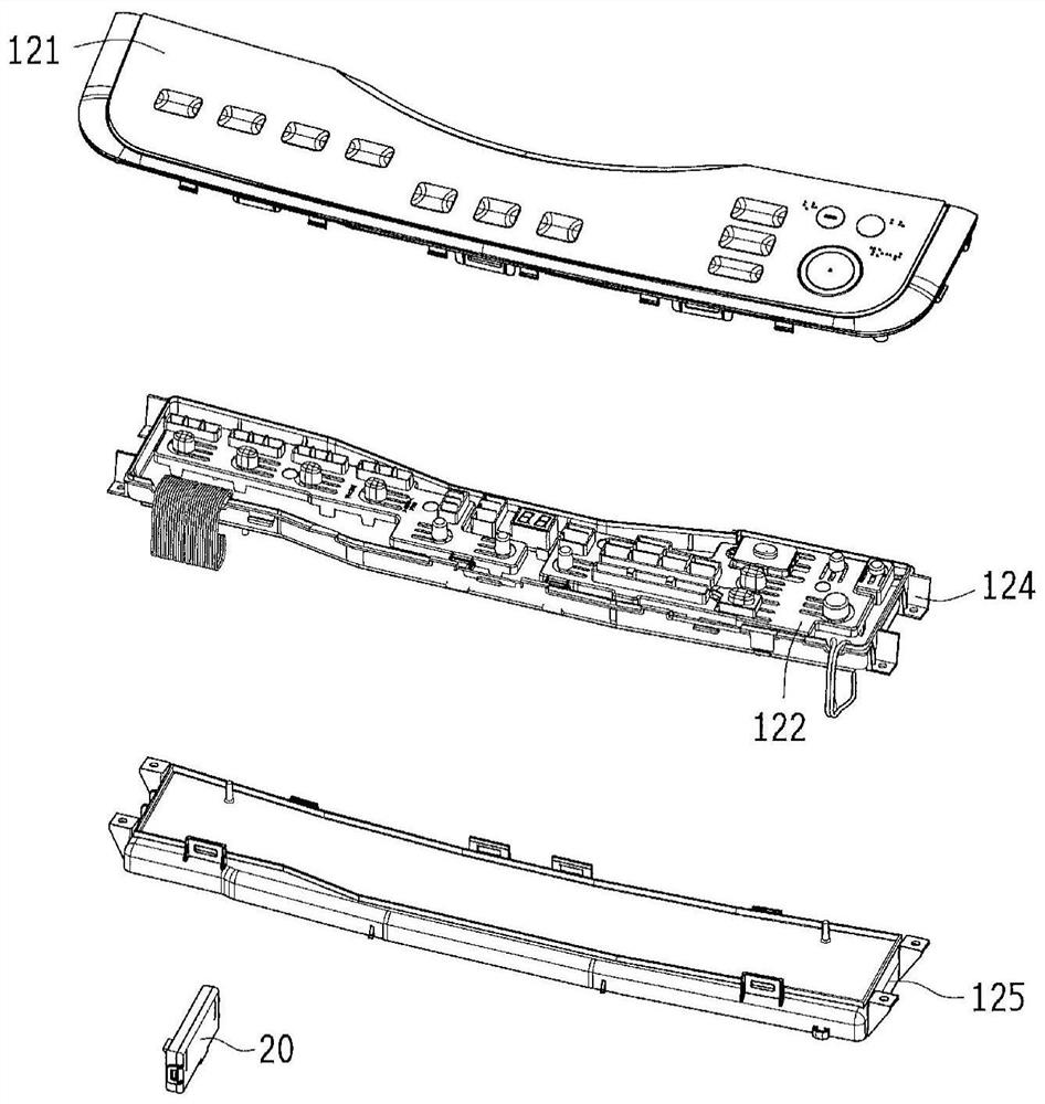
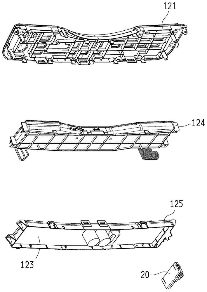
[0032] The washing machine 10 is capable of wireless communication with the Internet or a terminal device serving as a home server, and therefore has a wireless modu...
Embodiment approach 2
[0048] In Embodiment 2, another preferred configuration example of the wireless module 20 in the washing machine 10 will be described.
[0049] As described above, the wireless module 20 is configured such that the wireless communication substrate 22 is accommodated inside the module case 21 . and, if Figure 2 to Figure 4 As shown, in the wireless module 20 mounted in the washing machine 10, the circuit formation surface of the wireless communication substrate 22 is arranged to be a vertical surface (the circuit formation surface is parallel to the vertical direction). With this arrangement, even if water entering through the gap of the module case 21 splashes onto the circuit formation surface of the wireless communication board 22 , the water flows downward due to gravity, and the influence on the wireless communication board 22 can be minimized.
[0050] In addition, the arrangement in which the circuit formation surface of the wireless communication substrate 22 is a ver...
Embodiment approach 3
[0054] In Embodiment 3, a preferred example of the internal structure of the wireless module 20 will be described.
[0055] A pattern antenna for communication is formed on the wireless communication substrate 22 in the wireless module 20 . and, if Figure 5 As shown in (b), on the wireless communication substrate 22 , the area where the pattern antenna is formed is preferably the front end of the washing machine 10 .
[0056] Thus, if Figure 6 As shown, the pattern antenna of the wireless module 20 is located farthest from the dehydration tub provided inside the washing machine 10 in plan view. Since the dehydration bucket is made of stainless steel, the pattern antenna may have an adverse effect on communication performance when located close to the dehydration bucket, but by placing the pattern antenna away from the dehydration bucket, the adverse effect of the dehydration bucket on communication performance can be minimized minimize.
PUM
 Abstract
Description
Claims
Application Information
 - R&D
- Intellectual Property
- Life Sciences
- Materials
- Tech Scout
- Unparalleled Data Quality
- Higher Quality Content
- 60% Fewer Hallucinations
Browse by: Latest US Patents, China's latest patents, Technical Efficacy Thesaurus, Application Domain, Technology Topic, Popular Technical Reports.
© 2025 PatSnap. All rights reserved.Legal|Privacy policy|Modern Slavery Act Transparency Statement|Sitemap|About US| Contact US: help@patsnap.com


